
Description
• Up to four CT inputs per unit
• Omron’s proven heater burnout detection function
• Monitoring of CT currents to detect heater burnouts and SSR failures
• Time-proportional control outputs to drive SSRs
• Control outputs not affected by controller cycle time
• Four control outputs to drive SSRs (100 mA max.)
• Heater burnout detection for a single-phase or three-phase heater
• Detachable front connector with screwless Push-In Plus terminals for easy installation and maintenance
Sysmac is a trademark or registered trademark of OMRON Corporation in Japan and other countries for OMRON factory automation products.
EtherCAT® is a registered trademark of Beckhoff Automation GmbH for their patented technology.
EtherNet/IPTM is the trademarks of ODVA.
Other company names and product names in this document are the trademarks or registered trademarks of their respective companies.
Applicable standards
Refer to the OMRON website (www.ia.omron.com) or ask your OMRON representative for the most recent applicable standards for each model.
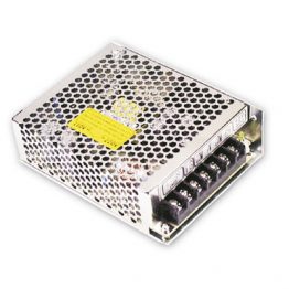
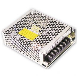
Heater Burnout Detection Unit
| Product name |
Specification | Model | ||||||
|---|---|---|---|---|---|---|---|---|
| CT input section | Control output section | |||||||
| Number of inputs |
Maximum heater current |
Number of outputs |
Internal I/O common |
Maximum load current |
Rated voltage |
I/O refreshing method |
||
| Heater Burnout Detection Unit  |
4 | 50 A AC | 4 | NPN | 0.1 A/point, 0.4 A/Unit |
12 to 24 VDC |
Free-Run refreshing |
NX-HB3101 |
| PNP | 24 VDC | NX-HB3201 | ||||||
Optional Products
| Product name | Specification | Model |
|---|---|---|
| Unit/Terminal Block Coding Pins | Pins for 10 Units (30 terminal block pins and 30 Unit pins) | NX-AUX02 |
| Product name | Specification | Model | |||
|---|---|---|---|---|---|
| No. of terminals |
Terminal number indications |
Ground terminal mark |
Terminal current capacity |
||
| Terminal Block | 16 | A/B | Not provided | 10 A | NX-TBA162 |
| Product name | Specification | Model |
|---|---|---|
| Current Transformer (CT) * | Hole diameter: 5.8 mm | E54-CT1 |
| Hole diameter: 12.0 mm | E54-CT3 |
* Can be connected to the NX-HB Heater Burnout Detection Unit.
Accessories
Not included.
General Specification
| Item | Specification | |
|---|---|---|
| Enclosure | Mounted in a panel | |
| Grounding method | Ground to 100 Ω or less | |
| Operating environment |
Ambient operating temperature |
0 to 55°C |
| Ambient operating humidity |
10% to 95% (with no condensation or icing) | |
| Atmosphere | Must be free from corrosive gases. | |
| Ambient storage temperature |
-25 to 70°C (with no condensation or icing) | |
| Altitude | 2,000 m max. | |
| Pollution degree | 2 or less: Conforms to JIS B3502 and IEC 61131-2. | |
| Noise immunity | 2 kV on power supply line (Conforms to IEC61000-4-4.) | |
| Overvoltage category | Category II: Conforms to JIS B3502 and IEC 61131-2. | |
| EMC immunity level | Zone B | |
| Vibration resistance | Conforms to IEC 60068-2-6. 5 to 8.4 Hz with 3.5-mm amplitude, 8.4 to 150 Hz, acceleration of 9.8 m/s2, 100 min each in X, Y, and Z directions (10 sweeps of 10 min each = 100 min total) |
|
| Shock resistance | Conforms to IEC 60068-2-27. 147 m/s2, 3 times each in X, Y, and Z directions | |
| Applicable standards * | cULus: Listed (UL508), ANSI/ISA 12.12.01, EU: EN 61131-2, C-Tick or RCM, KC Registration, NK, LR |
|
* Ask your OMRON representative for the most recent applicable standards for each model.
Function Specification
| Function | Description |
|---|---|
| Free-Run Refreshing | With this I/O refreshing method, the refresh cycle of the NX bus and I/O refresh cycles of the NX Units are asynchronous. |
| CT Allocation | This function is used to assign each CT input to a corresponding control output. |
| Reading CT Currents | This function reads CT inputs as heater currents or leakage currents. |
| Heater Burnout Detection | This function detects heater burnouts. A heater burnout is detected if the control output is ON and the heater current is equal to or less than the heater burnout detection current. |
| SSR Failure Detection | This function detects SSR failures. An SSR failure is detected if the control output is OFF and the leakage current is equal to or greater than the detection current. An SSR failure is a failure that is caused by an SSR short-circuit. |
| Time-proportional Output | This function controls a control output by using the manipulated variable from the host controller as a duty ratio. You can also specify the minimum pulse widths and execute immediate output commands. |
| Load Rejection Output Setting |
This function performs a preset output operation when the Heater Burnout Detection Unit cannot receive an output set value due to a communications error between the host and the Communications Coupler Unit or due to an error on the NX bus. |
| Load Short-circuit Protection |
This function is used to protect the output circuits of the Heater Burnout Detection Unit when an external device short-circuits. This function is supported only by the NX-HB3201. |
Heater Burnout Detection Unit
Heater Burnout Detection Unit (NPN) NX-HB3101
| Unit name | Heater Burnout Detection Unit | Model | NX-HB3101 | ||
|---|---|---|---|---|---|
| Number of points |
4 CT inputs and 4 control outputs | External connection terminals |
Screwless Clamping Terminal Block (16 terminals) |
||
| I/O refreshing method |
Free-Run refreshing | ||||
| Indicators | TS indicator and output indicators |
||||
| CT input section |
CT current input range |
0 to 0.125 A | Control output section |
Internal I/O common |
NPN |
| Input resistance |
Approx. 2.7 Ω | Control period | 50 to 100,000 ms | ||
| Connectable CTs |
E54-CT1 and E54-CT3 |
Manipulated variable |
0% to 100% | ||
| Resolution | 1 ms | ||||
| Rated voltage | 12 to 24 V DC | ||||
| Maximum heater current |
50 A AC | Operating load voltage range |
10.2 to 28.8 VDC | ||
| Resolution | 0.1 A | Maximum load current |
0.1 A/point, 0.4 A/Unit | ||
| Overall accuracy (25°C) |
±5% (full scale) ±1 digit |
Maximum inrush current |
1.0 A/point max., 10 ms | ||
| Leakage current | 0.1 mA max. | ||||
| Influence of temperature (0 to 55°C) |
±2% (full scale) ±1 digit |
Residual voltage | 1.5 V max. | ||
| Disconnection/ short-circuit detection |
None | ||||
| Conversion time |
10 ms | Protective functions |
None | ||
| Dimensions (mm) |
12 × 100 × 71 mm (W×H×D) | Isolation method |
Between control outputs and Internal circuits: Photocoupler isolation No isolation between Internal circuits and CT inputs |
||
| Insulation resistance |
20 MΩ min. between isolated circuits (at 100 VDC) | Dielectric strength |
510 VAC between isolated circuits for 1 minute with a leakage current of 5 mA max. |
||
| I/O power supply method |
Supplied from the NX bus. | Current capacity of I/O power supply terminals |
IOV: 0.1 A max. per terminal | ||
| NX Unit power consumption |
• Connected to a CPU Unit 1.05 W max. • Connected to a Communications Coupler Unit 0.75 W max. |
Current consumption from I/O power supply |
20 mA max. | ||
| Weight | 70 g max. | ||||
| Circuit configuration |
 |
||||
| Installation method and restrictions |
Installation orientation: • Connected to a CPU Unit: Possible in upright installation. • Connected to a Communications Coupler Unit: Possible in 6 orientations. Restrictions: No restrictions |
||||
| Terminal connection diagram |
 |
||||
Heater Burnout Detection Unit (PNP) NX-HB3201
| Unit name | Heater Burnout Detection Unit | Model | NX-HB3201 | ||
|---|---|---|---|---|---|
| Number of points |
4 CT inputs and 4 control outputs | External connection terminals |
Screwless Clamping Terminal Block (16 terminals) |
||
| I/O refreshing method |
Free-Run refreshing | ||||
| Indicators | TS indicator and output indicators |
||||
| CT input section |
CT current input range |
0 to 0.125 A | Control output section |
Internal I/O common |
PNP |
| Input resistance | Approx. 2.7 Ω | Control period | 50 to 100,000 ms | ||
| Connectable CTs | E54-CT1 and E54-CT3 |
Manipulated variable |
0% to 100% | ||
| Resolution | 1 ms | ||||
| Rated voltage | 24 VDC | ||||
| Maximum heater current |
50 A AC | Operating load voltage range |
15 to 28.8 VDC | ||
| Resolution | 0.1 A | Maximum load current |
0.1 A/point, 0.4 A/Unit | ||
| Overall accuracy (25°C) |
±5% (full scale) ±1 digit |
Maximum inrush current |
1.0 A/point max., 10 ms | ||
| Leakage current | 0.1 mA max. | ||||
| Influence of temperature (0 to 55°C) |
±2% (full scale) ±1 digit |
Residual voltage | 1.5 V max. | ||
| Disconnection/ short-circuit detection |
None | ||||
| Conversion time | 10 ms | Protective functions |
Provided. | ||
| Dimensions (mm) |
12 × 100 × 71 mm (W×H×D) | Isolation method |
Between control outputs and Internal circuits: Photocoupler isolation No isolation between Internal circuits and CT inputs |
||
| Insulation resistance |
20 MΩ min. between isolated circuits (at 100 VDC) |
Dielectric strength |
510 VAC between isolated circuits for 1 minute with a leakage current of 5 mA max. |
||
| I/O power supply method |
Supplied from the NX bus. | Current capacity of I/O power supply terminals |
IOV: 0.1 A max. per terminal | ||
| NX Unit power consumption |
• Connected to a CPU Unit 1.05 W max. • Connected to a Communications Coupler Unit 0.75 W max. |
Current consumption from I/O power supply |
20 mA max. | ||
| Weight | 70 g max. | ||||
| Circuit configuration |
 |
||||
| Installation method and restrictions |
Installation orientation: • Connected to a CPU Unit: Possible in upright installation. • Connected to a Communications Coupler Unit: Possible in 6 orientations. Restrictions: No restrictions |
||||
| Terminal connection diagram |
 |
||||
Version Information
Connected to a CPU Unit
Refer to the user’s manual for details on the CPU Units for the CPU Unit to which NX Units can be connected.
Heater Burnout Detection Units
| NX Unit | Corresponding unit versions/versions | ||
|---|---|---|---|
| Model | Unit version | CPU Unit | Sysmac Studio |
| NX-HB3101 | Ver.1.0 | Ver.1.13 | Ver.1.17 |
| NX-HB3201 | |||
Note: Some Units do not have all of the versions given in the above table. If a Unit does not have the specified version, support is provided by the oldest available version after the specified version. Refer to the user’s manuals for the specific Units for the relation between models and versions.
Connected to an EtherCAT Coupler Unit
Heater Burnout Detection Units
| NX Unit | Corresponding unit versions/versions | |||
|---|---|---|---|---|
| Model | Unit version | EtherCAT Coupler Unit |
CPU Unit or Industrial PC |
Sysmac Studio |
| NX-HB3101 | Ver.1.0 | Ver.1.0 | Ver.1.05 | Ver.1.16 |
| NX-HB3201 | ||||
Note: Some Units do not have all of the versions given in the above table. If a Unit does not have the specified version, support is provided by the oldest available version after the specified version. Refer to the user’s manuals for the specific Units for the relation between models and versions.
Connected to an EtherNet/IP Coupler Unit
Heater Burnout Detection Units
| NX Unit | Corresponding unit versions/versions | ||||||
|---|---|---|---|---|---|---|---|
| Model | Unit version |
Application with an NJ/NX/NY-series Controller *1 |
Application with a CS/CJ/CP-series PLC *2 |
||||
| EtherNet/IP Coupler Unit |
CPU Unit or Industrial PC |
Sysmac Studio |
EtherNet/IP Coupler Unit |
Sysmac Studio |
NX-IO Configurator *3 |
||
| NX-HB3101 | Ver.1.0 | Ver.1.2 | Ver.1.14 | Ver.1.19 | Ver.1.0 | Ver.1.16 | Ver.1.00 |
| NX-HB3201 | |||||||
Note: Some Units do not have all of the versions given in the above table. If a Unit does not have the specified version, support is provided by the oldest available version after the specified version. Refer to the user’s manuals for the specific Units for the relation between models and versions.
*1. Refer to the user’s manual of the EtherNet/IP Coupler Unit for the unit versions of EtherNet/IP Units corresponding to EtherNet/IP Coupler Units.
*2. Refer to the user’s manual of the EtherNet/IP Coupler Unit for the unit versions of CPU Units and EtherNet/IP Units corresponding to EtherNet/IP Coupler Units.
*3. For connection to an EtherNet/IP Coupler Unit with unit version 1.0, connection is supported only for a connection to the peripheral USB port on the EtherNet/IP Coupler Unit. You cannot connect by any other path. If you need to connect by another path, use an EtherNet/IP Coupler Unit with unit version 1.2 or later.
Connected to an Communication Control Unit
Heater Burnout Detection Units
| NX Unit | Corresponding unit versions/versions | ||
|---|---|---|---|
| Model | Unit version | Communication Control Unit | Sysmac Studio |
| NX-HB3101 | Ver.1.0 | — | — |
| NX-HB3201 | |||
Note: 1. Some Units do not have all of the versions given in the above table. If a Unit does not have the specified version, support is provided by the oldest available version after the specified version. Refer to the user’s manuals for the specific Units for the relation between models and versions.
Note: 2. You cannot connect the relevant NX Unit to the Communication Control Unit if “—” is shown in the corresponding unit versions/versions column.
(Unit: mm)
Screwless Clamping Terminal Block Type
12 mm Width

* The dimension is 1.35 mm for Units with lot numbers through December 2014.
|
Catalog Name
|
Catalog Number
[size] |
Last Update
|
|---|---|---|
| – [5191KB] |
Aug 01, 2018 | |
| R183-E1-09 [6683KB] |
Nov 01, 2018 |


Reviews
There are no reviews yet.