
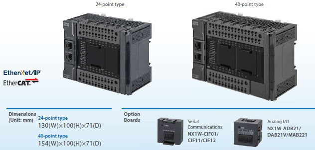
Description
Advanced motion control and networks for onsite IoT in a Sysmac entry model
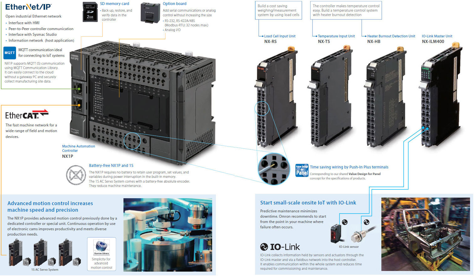
Advanced motion control
The built-in EtherCAT port and advanced motion control make machines faster and more precise
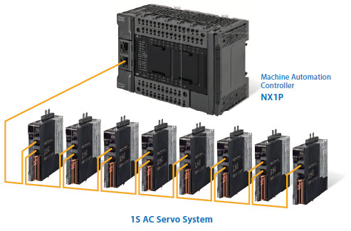
• EtherCAT simplifies the wiring to up to eight servo systems including for single-axis position control.
• Up to four axes of motion control. Electronic cams and interpolation increase machine speed and precision.
Interpolation
• Linear interpolation and circular interpolation for precise machining and high-speed handling
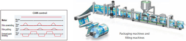
Electronic cam
• Electronic cam enables continuous and high-speed machine operation
• Electronic cam makes it possible to easily change operation timing via a program through computerized cam operation to meet diverse production needs, which is difficult with mechanical cam

Data transmission delay is compensated to synchronize servomotors.
Synchronized axes provide high-precision positioning.
• EtherCAT enables one cable to connect the NX1P with servo drives, reducing wiring work.
1S AC Servo System
1S AC Servo System
• No battery, no maintenance. No need for homing sequence improving machine uptime
• 23 bit high resolution encoder as standard
• Improved loop control for low overshoot and quick settling time
• Safety function: STO
Networks for onsite IoT
IO-Link brings IoT to the sensor level
You can check machine information by monitoring the status of the connected components.
• EtherNet/IP enables communications with a host PC and data links between NJ/NX Controllers and CJ PLCs.

Predictive maintenance using IO-Link
You can start predictive maintenance with visualization of the status of a small-sized machine.
IO-Link functionality can be added to existing machines.

Product line up
Machine Automation Controller NX-series
NX1P2 CPU Units
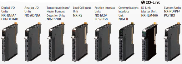
NX Series
Up to eight NX Units can be connected to an NX1P2 CPU Unit.
Automation Software Sysmac Studio
SYSMAC-SE2[][][]

The Sysmac Studio is the software that provides an integrated environment for setting, programming, debugging and maintenance of machine automation controllers including the NJ/NX CPU Units, EtherCAT Slave, and the HMI.
• Fully compliant with open standard IEC 61131-3 and Japanese standard JIS B3503
• Supports Ladder, Structured Text and Function Block programming with a rich instruction set
• CAM editor for easy programming of complex motion profiles
• One simulation tool for sequence and motion in a 3D environment
• Advanced security function with 32 digit security password
Sysmac is a trademark or registered trademark of OMRON Corporation in Japan and other countries for OMRON factory automation products.
Windows is either registered trademarks or trademarks of Microsoft Corporation in the United States and/or other countries.
EtherCAT® is registered trademark and patented technology, licensed by Beckhoff Automation GmbH, Germany.
EtherNet/IP™ is the trademarks of ODVA.
Other company names and product names in this document are the trademarks or registered trademarks of their respective companies.
The product photographs and figures that are used in this catalog may vary somewhat from the actual products.
Microsoft product screen shot(s) reprinted with permission from Microsoft Corporation.
International Standards
• The standards are abbreviated as follows: U: UL, U1: UL (Class I Division 2 Products for Hazardous Locations), C: CSA, UC: cULus, UC1: cULus (Class I Division 2 Products for Hazardous Locations), CU: cUL, N: NK, L: Lloyd, CE: EU Directives, EAC: EAC mark, RCM: Regulatory Compliance Mark and KC: KC Registration.
• Contact your OMRON representative for further details and applicable conditions for these standards.
NX-series NX1P2 CPU Units
| Product Name |
Pro- gram ca- paci- ty |
Memory capacity for variables |
Maximum number of used real axes |
Total number of built-in I/O points |
Model | Stand- ards |
||||
|---|---|---|---|---|---|---|---|---|---|---|
| Used motion control servo axes *1 |
Used single- axis position control servo axes *1 |
Number of input points |
Number of output points |
|||||||
| NX1P2 CPU Unit  |
1.5 MB |
32 KB (Retained during power inter- ruptions) or 2 MB (Not retained during power inter- ruptions) |
8 axes |
4 axes | 4 axes | 40 points |
24 points |
16 points, NPN transistor |
NX1P2-1140DT | UC1, N, L, CE, RCM, KC, EAC |
| 16 points, PNP transistor *2 |
NX1P2-1140DT1 | |||||||||
| 6 axes |
2 axes | 4 axes | 16 points, NPN transistor |
NX1P2-1040DT | ||||||
| 16 points, PNP transistor *2 |
NX1P2-1040DT1 | |||||||||
 |
4 axes |
0 axes | 4 axes | 24 points |
14 points |
10 points, NPN transistor |
NX1P2-9024DT | |||
| 10 points, PNP transistor *2 |
NX1P2-9024DT1 | |||||||||
Note: One NX-END02 End Cover is provided with the NX1P2 CPU Unit.
*1. The following table shows the enabled functions.
| Motion control function | Motion control servo axes | Single-axis position control servo axes |
|---|---|---|
| Single-axis position control | Yes | Yes |
| Single-axis synchronized control | Yes | No |
| Single-axis velocity control | Yes | Yes * |
| Single-axis torque control | Yes | No |
| Multi-axes coordinated control | Yes | No |
*You can use only the MC_MoveVelocity (Velocity Control) instruction.
*2. With the load short-circuit protection.
Option Boards (For CPU Units)
The Option Boards are mounted to the option board slot on the CPU Unit.
| Product Name | Specification | Supported protocol |
Model | Stand- ards |
|---|---|---|---|---|
| Serial Communications Option Board  |
One RS-232C port. Transmission distance: 15 m. Connection type: Screwless clamping terminal block (9 terminals). |
Host link, Modbus-RTU master, and no-protocol |
NX1W-CIF01 | UC1, L, CE, RCM, KC |
 |
One RS-422A/485 port. Transmission distance: 50 m. Connection type: Screwless clamping terminal block (5 terminals) |
NX1W-CIF11 | ||
| One RS-422A/485 port (isolated). Transmission distance: 500 m. Connection type: Screwless clamping terminal block (5 terminals) |
NX1W-CIF12 | |||
| Analog I/O Option Board  |
Analog input: 2 Voltage input: 0 to 10 V (Resolution: 1/4,000). Current input: 0 to 20 mA (1/2,000) Connection type: Screwless clamping terminal block (5 terminals) |
NX1W-ADB21 | ||
 |
Analog output: 2 Voltage output: 0 to 10 V (Resolution: 1/4,000) Connection type: Screwless clamping terminal block (3 terminals) |
NX1W-DAB21V | ||
 |
Analog input: 2/Analog output: 2 Voltage input: 0 to 10 V (Resolution: 1/4,000). Current input: 0 to 20 mA (1/2,000) Voltage output: 0 to 10 V (Resolution: 1/4,000) Screwless clamping terminal block (8 terminals) |
NX1W-MAB221 | ||
NX Units
Up to eight NX Units can be connected to an NX1P2 CPU Unit.
Digital Input Units
| Product Name | Specification | Model | Standards | ||||
|---|---|---|---|---|---|---|---|
| Number of points |
Internal I/O common |
Rated input voltage |
I/O refreshing method |
ON/OFF response time |
|||
DC Input Unit (Screwless Clamping Terminal Block, 12 mm Width) |
4 points | NPN | 12 to 24 VDC |
Switching Synchronous I/O refreshing and Free- Run refreshing |
20 μs max./ 400 μs max. |
NX-ID3317 | UC1, N, L, CE, RCM, KC |
| 24 VDC | 100 ns max./ 100 ns max. |
NX-ID3343 | |||||
| Input refreshing with input changed time only * |
NX-ID3344 | ||||||
| PNP | 12 to 24 VDC |
Switching Synchronous I/O refreshing and Free- Run refreshing |
20 μs max./ 400 μs max. |
NX-ID3417 | |||
| 24 VDC | 100 ns max./ 100 ns max. |
NX-ID3443 | |||||
| Input refreshing with input changed time only * |
NX-ID3444 | ||||||
| 8 points | NPN | Switching Synchronous I/O refreshing and Free- Run refreshing |
20 μs max./ 400 μs max. |
NX-ID4342 | |||
| PNP | NX-ID4442 | ||||||
| 16 points | NPN | NX-ID5342 | |||||
| PNP | NX-ID5442 | ||||||
DC Input Unit (M3 Screw Terminal Block, 30 mm Width) |
16 points | For both NPN/PNP |
24 VDC | Switching Synchronous I/O refreshing and Free- Run refreshing |
20 μs max./ 400 μs max. |
NX-ID5142-1 | |
DC Input Unit (MIL Connector, 30 mm Width) |
16 points | For both NPN/PNP |
24 VDC | Switching Synchronous I/O refreshing and Free- Run refreshing |
20 μs max./ 400 μs max. |
NX-ID5142-5 | |
| 32 points | NX-ID6142-5 | ||||||
DC Input Unit (Fujitsu Connector, 30 mm Width) |
32 points | For both NPN/PNP |
24 VDC | Switching Synchronous I/O refreshing and Free- Run refreshing |
20 μs max./ 400 μs max. |
NX-ID6142-6 | |
AC Input Unit (Screwless Clamping Terminal Block, 12 mm Width) |
4 points | 200 to 240 VAC, 50/60 Hz (170 to 264 VAC, ±3 Hz) |
Free-Run refreshing | 10 ms max./ 40 ms max. |
NX-IA3117 | UC1, N, CE, RCM, KC |
|
Sysmac Studio version 1.07 or higher are required.
Digital output Units
| Product Name |
Specification | Model | Stand- ards |
|||||
|---|---|---|---|---|---|---|---|---|
| Number of points |
Internal I/O common |
Maximum value of load current |
Rated voltage |
I/O refreshing method |
ON/OFF response time |
|||
| Transistor Output Unit  (Screwless Clamping Terminal Block, 12 mm Width) |
2 points |
NPN | 0.5 A/point, 1 A/Unit |
24 VDC | Output refreshing with specified time stamp only * |
300 ns max./ 300 ns max. |
NX-OD2154 | UC1, N, L, CE, RCM, KC |
| PNP | NX-OD2258 | |||||||
| 4 points |
NPN | 0.5 A/point, 2 A/Unit |
12 to 24 VDC |
Switching Synchronous I/O refreshing and Free-Run refreshing |
0.1 ms max./ 0.8 ms max. |
NX-OD3121 | ||
| 24 VDC | 300 ns max./ 300 ns max. |
NX-OD3153 | ||||||
| PNP | 0.5 ms max./ 1.0 ms max. |
NX-OD3256 | ||||||
| 300 ns max./ 300 ns max. |
NX-OD3257 | |||||||
| 2 A/point, 8 A/Unit |
0.5 ms max./ 1.0 ms max. |
NX-OD3268 | ||||||
| 8 points |
NPN | 0.5 A/point, 4 A/Unit |
12 to 24 VDC |
0.1 ms max./ 0.8 ms max. |
NX-OD4121 | |||
| PNP | 24 VDC | 0.5 ms max./ 1.0 ms max. |
NX-OD4256 | |||||
| 16 points |
NPN | 12 to 24 VDC |
0.1 ms max./ 0.8 ms max. |
NX-OD5121 | ||||
| PNP | 24 VDC | 0.5 ms max./ 1.0 ms max. |
NX-OD5256 | |||||
| Transistor Output Unit  (M3 Screw Terminal Block, 30 mm Width) |
16 points |
NPN | 0.5 A/point, 5 A/Unit |
12 to 24 VDC |
Switching Synchronous I/O refreshing and Free-Run refreshing |
0.1 ms max./ 0.8 ms max. |
NX-OD5121-1 | |
| PNP | 24 VDC | 0.5 ms max./ 1.0 ms max. |
NX-OD5256-1 | |||||
| Transistor Output Unit  (MIL Con- nector, 30 mm Width) |
16 points |
NPN | 0.5 A/point, 2 A/Unit |
12 to 24 VDC |
Switching Synchronous I/O refreshing and Free-Run refreshing |
0.1 ms max./ 0.8 ms max. |
NX-OD5121-5 | |
| PNP | 24 VDC | 0.5 ms max./ 1.0 ms max. |
NX-OD5256-5 | |||||
| 32 points |
NPN | 0.5 A/point, 2 A/ common, 4 A/Unit |
12 to 24 VDC |
0.1 ms max./ 0.8 ms max. |
NX-OD6121-5 | |||
| PNP | 24 VDC | 0.5 ms max./ 1.0 ms max. |
NX-OD6256-5 | |||||
| Transistor Output Unit  (Fujitsu Connector, 30 mm Width) |
32 points |
NPN | 0.5 A/point, 2 A/ common, 4 A/Unit |
12 to 24 VDC |
Switching Synchronous I/O refreshing and Free-Run refreshing |
0.1 ms max./ 0.8 ms max. |
NX-OD6121-6 | |
| Relay Output Unit  (Screwless Clamping Terminal Block, 12 mm Width/ 24 mm Width) |
2 points |
N.O. | 250 VAC/2 A (cosφ=1) 250 VAC/2 A (cosφ=0.4) 24 VDC/2 A 4 A/Unit |
Free-Run refreshing |
15 ms max./ 15 ms max. |
NX-OC2633 | UC1, N, L, CE, RCM, KC |
|
| N.O.+ N.C. |
NX-OC2733 | UC1, N, CE, RCM, KC |
||||||
| 8 points |
N.O. | 250 VAC/2 A (cosφ=1) 250 VAC/2 A (cosφ=0.4) 24 VDC/2 A 8 A/Unit |
Free-Run refreshing |
15 ms max./ 15 ms max. |
NX-OC4633 | UC1, N, L, CE, EAC, RCM, KC |
||
* To use input refreshing with input changed time, the EtherCAT Coupler Unit with unit version 1.1 or later and the Sysmac Studio version 1.07 or higher are required.
Digital Mixed I/O Units
| Product Name | Specification | Model | Standards | ||||
|---|---|---|---|---|---|---|---|
| Number of points |
Internal I/O common |
Maximum value of load current |
I/O refreshing method |
ON/OFF response time |
|||
| DC Input/ Transistor Output Unit  (MIL Connector, 30 mm Width) |
Outputs: 16 points Inputs: 16 points |
Outputs: NPN Inputs: For both NPN/PNP |
Outputs: 12 to 24 VDC Inputs: 24 VDC |
Switching Synchronous I/O refreshing and Free-Run refreshing |
Outputs: 0.1 ms max./ 0.8 ms max. Inputs: 20 μs max./ 400 μs max. |
NX-MD6121-5 | UC1, N, L, CE, RCM, KC |
| Outputs: PNP Inputs: For both NPN/PNP |
Outputs: 24 VDC Inputs: 24 VDC |
Outputs: 0.5 ms max./ 1.0 ms max. Inputs: 20 μs max./ 400 μs max. |
NX-MD6256-5 | ||||
| DC Input/ Transistor Output Unit  (Fujitsu Connector, 30 mm Width) |
Outputs: 16 points Inputs: 16 points |
Outputs: NPN Inputs: For both NPN/PNP |
Outputs: 12 to 24 VDC Inputs: 24 VDC |
Switching Synchronous I/O refreshing and Free-Run refreshing |
Outputs: 0.1 ms max./ 0.8 ms max. Inputs: 20 μs max./ 400 μs max. |
NX-MD6121-6 | |
High-speed Analog Input Units
| Product name |
Specifications | Model | Stan- dards |
|||||||
|---|---|---|---|---|---|---|---|---|---|---|
| Num- ber of points |
Input range |
Resolution | Input method |
Con- version time |
Trigger input section |
I/O refreshing method |
||||
| Number of points |
Internal I/O common |
|||||||||
| High- speed Analog Input Unit  |
4 | -10 to 10 V -5 to 5 V 0 to 10 V 0 to 5 V 1 to 5 V 0 to 20 mA 4 to 20 mA |
• Input range of -10 to 10 V or -5 to 5 V: 1/64,000 (full scale) • Other input range: 1/32,000 (full scale) |
Diffe- rential input |
5 μs per channel |
4 | NPN | Synch- ronous I/O refreshing |
NX-HAD401 | UC1, CE, RCM, KC, EAC |
| PNP | NX-HAD402 | |||||||||
Analog Input Units
| Product Name |
Specification | Model | Stand- ards |
||||||||
|---|---|---|---|---|---|---|---|---|---|---|---|
| Num- ber of points |
Input range |
Reso- lution |
Con- version value, decimal number (0 to 100%) |
Over all accuracy (25°C) |
Input method |
Con- ver- sion time |
Input im- ped- ance |
I/O re- freshing method |
|||
| Voltage Input Unit  |
2 points |
-10 to +10 V |
1/8000 | -4000 to 4000 |
±0.2% (full scale) |
Single- ended input |
250 μs/ point |
1 MΩ min. |
Free-Run refreshing |
NX-AD2603 | UC1, N, L, CE, RCM, KC |
| Differ- ential Input |
NX-AD2604 | ||||||||||
| 1/30000 | -15000 to 15000 |
±0.1% (full scale) |
Differ- ential Input |
10 μs/ point |
Selectable Synchro- nous I/O refreshing or Free- Run re- freshing |
NX-AD2608 | |||||
| 4 points |
1/8000 | -4000 to 4000 |
±0.2% (full scale) |
Single- ended input |
250 μs/ point |
Free-Run refreshing |
NX-AD3603 | ||||
| Differ- ential Input |
NX-AD3604 | ||||||||||
| 1/30000 | -15000 to 15000 |
±0.1% (full scale) |
Differ- ential Input |
10 μs/ point |
Selectable Synchro- nous I/O refreshing or Free- Run re- freshing |
NX-AD3608 | |||||
| 8 points |
1/8000 | -4000 to 4000 |
±0.2% (full scale) |
Single- ended input |
250 μs/ point |
Free-Run refreshing |
NX-AD4603 | ||||
| Differ- ential Input |
NX-AD4604 | ||||||||||
| 1/30000 | -15000 to 15000 |
±0.1% (full scale) |
Differ- ential Input |
10 μs/ point |
Selectable Synchro- nous I/O refreshing or Free- Run re- freshing |
NX-AD4608 | |||||
| Current Input Unit  |
2 points |
4 to 20 mA |
1/8000 | 0 to 8000 |
±0.2% (full scale) |
Single- ended input |
250 μs/ point |
250 Ω |
Free-Run refreshing |
NX-AD2203 | |
| Differ- ential Input |
NX-AD2204 | ||||||||||
| 1/30000 | 0 to 30000 |
±0.1% (full scale) |
Differ- ential Input |
10 μs/ point |
Selectable Synchro- nous I/O refreshing or Free- Run re- freshing |
NX-AD2208 | |||||
| 4 points |
1/8000 | 0 to 8000 |
±0.2% (full scale) |
Single- ended input |
250 μs/ point |
Free-Run refreshing |
NX-AD3203 | ||||
| Differ- ential Input |
NX-AD3204 | ||||||||||
| 1/30000 | 0 to 30000 |
±0.1% (full scale) |
Differ- ential Input |
10 μs/ point |
Selectable Synchro- nous I/O refreshing or Free- Run re- freshing |
NX-AD3208 | |||||
| 8 points |
1/8000 | 0 to 8000 |
±0.2% (full scale) |
Single- ended input |
250 μs/ point |
85 Ω |
Free-Run refreshing |
NX-AD4203 | |||
| Differ- ential Input |
NX-AD4204 | ||||||||||
| 1/30000 | 0 to 30000 |
±0.1% (full scale) |
Differ- ential Input |
10 μs/ point |
Selectable Synchro- nous I/O refreshing or Free- Run re- freshing |
NX-AD4208 | |||||
Analog Output Units
| Product Name |
Specification | Model | Stand- ards |
||||||
|---|---|---|---|---|---|---|---|---|---|
| Number of points |
Input range |
Reso- lution |
Output setting value, decimal number (0 to 100%) |
Over all accuracy (25°C) |
Con- version time |
I/O refreshing method |
|||
| Voltage Output Unit  |
2 points | -10 to +10 V |
1/8000 | -4000 to 4000 | ±0.3% (full scale) |
250 μs/ point |
Free-Run refreshing |
NX-DA2603 | UC1, N, L, CE, RCM, KC |
| 1/30000 | -15000 to 15000 |
±0.1% (full scale) |
10 μs/ point |
Selectable Synchronous I/O refreshing or Free-Run refreshing |
NX-DA2605 | ||||
| 4 points | 1/8000 | -4000 to 4000 | ±0.3% (full scale) |
250 μs/ point |
Free-Run refreshing |
NX-DA3603 | |||
| 1/30000 | -15000 to 15000 |
±0.1% (full scale) |
10 μs/ point |
Selectable Synchronous I/O refreshing or Free-Run refreshing |
NX-DA3605 | ||||
| Current Output Unit  |
2 points | 4 to 20 mA |
1/8000 | 0 to 8000 | ±0.3% (full scale) |
250 μs/ point |
Free-Run refreshing |
NX-DA2203 | |
| 1/30000 | 0 to 30000 | ±0.1% (full scale) |
10 μs/ point |
Selectable Synchronous I/O refreshing or Free-Run refreshing |
NX-DA2205 | ||||
| 4 points | 1/8000 | 0 to 8000 | ±0.3% (full scale) |
250 μs/ point |
Free-Run refreshing |
NX-DA3203 | |||
| 1/30000 | 0 to 30000 | ±0.1% (full scale) |
10 μs/ point |
Selectable Synchronous I/O refreshing or Free-Run refreshing |
NX-DA3205 | ||||
Temperature Control Units
| Product name |
Specifications | Model | Stan- dards |
|||||||
|---|---|---|---|---|---|---|---|---|---|---|
| Number of channels |
Input type |
Output | Number of output points |
Number of CT input points |
Control type |
Con- version time |
I/O refreshing method |
|||
| Tempe- rature Control Unit 2-channel Type  |
2 | Universal input (thermo- couple, resistance thermo- meter) |
Voltage output (for driving SSR) |
2 | 2 | Standard control |
50 ms | Free-Run refreshing |
NX-TC2405 | UC1, CE, RCM, KC, EAC |
| None | Standard control |
NX-TC2406 | ||||||||
| Voltage output (for driving SSR) |
4 | None | Heating/ cooling control |
NX-TC2407 | ||||||
| Linear current output |
2 | None | Standard control |
NX-TC2408 | ||||||
| Temper- ature Control Unit 4-channel Type  |
4 | Voltage output (for driving SSR) |
4 | 4 | Standard control |
NX-TC3405 | UC1, CE, RCM, KC, EAC |
|||
| None | Standard control |
NX-TC3406 | ||||||||
| Voltage output (for driving SSR) |
8 | None | Heating/ cooling control |
NX-TC3407 | ||||||
| Linear current output |
4 | None | Standard control |
NX-TC3408 | ||||||
Temperature Input Units
| Product Name |
Specification | Model | Standa- rds |
||||||
|---|---|---|---|---|---|---|---|---|---|
| Number of points |
Input type |
Re- solution (25°C) |
Over all accuracy (25°C) |
Con- version time |
I/O re- fresh- ing method |
Terminals | |||
| Thermo- couple Input type  |
2 points | Thermo- couple |
0.1°C max. *1 |
Refer to your OMRON website for details. |
250 ms/ Unit |
Free- Run re- freshing |
16 Terminals |
NX-TS2101 | UC1, N, L, CE, RCM, KC |
| 4 points | 16 Ter- minals x 2 |
NX-TS3101 | |||||||
| 2 points | 0.01°C max. |
10 ms/ Unit |
16 Terminals |
NX-TS2102 | |||||
| 4 points | 16 Ter- minals x 2 |
NX-TS3102 | |||||||
| 2 points | 0.001°C max. |
60 ms/ Unit |
16 Terminals |
NX-TS2104 | |||||
| 4 points | 16 Ter- minals x 2 |
NX-TS3104 | |||||||
| Re- sistance Thermo- meter Input type  |
2 points | Re- sistance Thermo- meter (Pt100/ Pt1000, three- wire) *2 |
0.1°C max. |
250 ms/ Unit |
16 Terminals |
NX-TS2201 | |||
| 4 points | 16 Ter- minals x 2 |
NX-TS3201 | |||||||
| 2 points | 0.01°C max. |
10 ms/ Unit |
16 Terminals |
NX-TS2202 | |||||
| 4 points | 16 Ter- minals x 2 |
NX-TS3202 | |||||||
| 2 points | 0.001°C max. |
60 ms/ Unit |
16 Terminals |
NX-TS2204 | |||||
| 4 points | 16 Ter- minals x 2 |
NX-TS3204 | |||||||
*1. The resolution is 0.2°C max. when the input type is R, S, or W.
*2. The NX-TS2202 and NX-TS3202 only supports Pt100 three-wire sensor.
Heater Burnout Detection Units
| Product Name |
Specification | Model | Stand- ards |
||||||
|---|---|---|---|---|---|---|---|---|---|
| CT input section | Control output section | ||||||||
| Number of inputs |
Maximum heater current |
Number of outputs |
Internal I/O common |
Maximum load current |
Rated voltage |
I/O refreshing method |
|||
| Heater Burnout Detection Unit  |
4 | 50 AAC | 4 | NPN | 0.1 A/point, 0.4 A/Unit |
12 to 24 VDC |
Free-Run refreshing |
NX-HB3101 | UC1, N, L, CE, RCM, KC |
| PNP | 24 VDC | NX-HB3201 | |||||||
Load Cell Input Unit
| Product Name |
Specification | Model | Standards | ||||
|---|---|---|---|---|---|---|---|
| Number of Model Standards points |
Conversion cycle |
I/O refreshing method * |
Load cell excitation voltage |
Input range |
|||
| Load Cell Input Unit  |
1 | 125 μs | • Free-Run refreshing • Synchronous I/O refreshing • Task period prioritized refreshing |
5 VDC ± 10% |
-5.0 to 5.0 mV/V |
NX-RS1201 | UC1, N, L, CE, RCM, KC |
* Refer to the NX-series Load Cell Input Unit User’s Manual (W565) for detailed information on I/O refresh cycle.
Position interface: Incremental Encoder Input Units
| Product Name |
Specification | Model | Standards | ||||
|---|---|---|---|---|---|---|---|
| Number of channels |
External inputs |
Maximum response frequency |
I/O refreshing method |
Number of I/O entry mappings |
|||
| Incremental Encoder Input Unit  |
1 (NPN) | 3 (NPN) | 500 kHz | • Free-Run refreshing • Synchronous I/O refreshing |
1/1 | NX-EC0112 | UC1, N, CE, RCM, KC |
| 1 (PNP) | 3 (PNP) | NX-EC0122 | UC1, N, L, CE, RCM, KC |
||||
| 1 | 3 (NPN) | 4 MHz | NX-EC0132 | UC1, N, CE, RCM, KC |
|||
| 3 (PNP) | NX-EC0142 | UC1, N, L, CE, RCM, KC |
|||||
| 2 (NPN) | None | 500 kHz | 2/2 | NX-EC0212 | UC1, N, CE, RCM, KC |
||
| 2 (PNP) | NX-EC0222 | UC1, N, L, CE, RCM, KC |
|||||
Position interface: SSI Input Units
| Product Name |
Specification | Model | Standards | ||||
|---|---|---|---|---|---|---|---|
| Number of channels |
Input/ Output form |
Maximum data length |
Encoder power supply |
Type of external connections |
|||
| SSI Input Unit  |
1 | EIA standard RS-422-A |
32 bits | 24 VDC, 0.3 A/CH |
Screwless push-in terminal block (12 terminals) |
NX-ECS112 | UC1, N, L, CE, RCM, KC |
| 2 | EIA standard RS-422-A |
32 bits | 24 VDC, 0.3 A/CH |
Screwless push-in terminal block (12 terminals) |
NX-ECS212 | ||
Position interface: Pulse Output Units
| Product Name |
Specification | Model | Stand- ards |
||||||
|---|---|---|---|---|---|---|---|---|---|
| Number of channels *1 |
External inputs |
External outputs |
Max- imum pulse output speed |
I/O refreshing method |
Number of I/O entry map- pings |
Control output inte- face |
|||
| Pulse Output Unit  |
1 (NPN) | 2 (NPN) | 1 (NPN) | 500 kpps |
• Synchronous I/O refreshing • Task period prioritized refreshing *2 |
1/1 | Open collector output |
NX-PG0112 | UC1, N, CE, RCM, KC |
| 1 (PNP) | 2 (PNP) | 1 (PNP) | NX-PG0122 | UC1, N, L, CE, RCM, KC |
|||||
| 2 | 5 inputs/ CH (NPN) |
3 outputs/ CH (NPN) |
4 Mpps |
2/2 | Line driver output |
NX-PG0232-5 | UC1, CE, RCM, KC |
||
| 5 inputs/ CH (PNP) |
3 outputs/ CH (PNP) |
NX-PG0242-5 | |||||||
| 4 | 5 inputs/ CH (NPN) |
3 outputs/ CH (NPN) |
4/4 | NX-PG0332-5 | |||||
| 5 inputs/ CH (PNP) |
3 outputs/ CH (PNP) |
NX-PG0342-5 | |||||||
*1. This is the number of pulse output channels.
*2. Unit version 1.2 or later and an NX-ECC203 EtherCAT Coupler Unit are required.
Communications Interface Units
| Product Name | Serial interface |
External connection terminals |
Number of serial ports |
Communications protocol |
Model | Standards |
|---|---|---|---|---|---|---|
| Communications Interface Unit  |
RS-232C | Screwless Clamping Terminal Block |
1 port | • No-protocol • Signal lines |
NX-CIF101 | UL, N, L, CE, RCM, KC |
| RS-422A/485 | NX-CIF105 | |||||
| RS-232C | D-Sub connector | 2 ports | NX-CIF210 |
IO-Link Master Unit
| Product Name | Specification | Model | Standards | ||
|---|---|---|---|---|---|
| Number of IO-Link ports |
I/O refreshing method |
I/O connection terminals |
|||
IO-Link Master Unit |
4 | Free-Run refreshing | Screwless clamping terminal block |
NX-ILM400 | UC1, N, L, CE, RCM, KC |
System Units
| Product Name | Specification | Model | Standards |
|---|---|---|---|
| Additional NX Unit Power Supply Unit  |
Power supply voltage: 24 VDC (20.4 to 28.8 VDC) NX Bus power supply capacity: 10 W max. |
NX-PD1000 | UC1, N, L, CE, RCM, KC |
| Additional I/O Power Supply Unit  |
Power supply voltage: 5 to 24 VDC (4.5 to 28.8 VDC) I/O power feed maximum current: 4 A |
NX-PF0630 | UC1, N, L, CE, RCM, KC |
| Power supply voltage: 5 to 24 VDC (4.5 to 28.8 VDC) I/O power feed maximum current: 10 A * |
NX-PF0730 | ||
| I/O Power Supply Connection Unit  |
Number of I/O power terminals: IOG: 16 terminals Current capacity of I/O power terminal: 4 A/terminal max. |
NX-PC0010 | UC1, N, L, CE, RCM, KC |
| Number of I/O power terminals: IOV: 16 terminals Current capacity of I/O power terminal: 4 A/terminal max. |
NX-PC0020 | UC1, N, L, CE, RCM, KC |
|
| Number of I/O power terminals: IOV: 8 terminals, IOG: 8 terminals Current capacity of I/O power terminal: 4 A/terminal max |
NX-PC0030 | UC1, N, L, CE, RCM, KC |
|
| Shield Connection Unit  |
Number of shield terminals: 14 terminals (The following two terminals are functional ground terminals.) |
NX-TBX01 | UC1, N, L, CE, RCM, KC |
* Use the NX-PF0730 at 4 A or less on the CPU Rack where the NX1P2 CPU Unit is mounted.
EtherCAT Coupler Units
NX-series Units on previous pages and NX-series Safety Units can be used by connecting to the EtherCAT Coupler Unit that is connected to the built-in EtherCAT port on the NX1P2 CPU Unit.
| Product Name | Communications cycle in DC Mode |
Current consumption |
Maximum I/O power supply current |
Model | Standards |
|---|---|---|---|---|---|
| EtherCAT Coupler Unit *1  |
250 to 4000 μs *2 | 1.45 W max. | 4 A | NX-ECC201 | UC1, N, L, CE, KC |
| 250 to 4000 μs *2 | 10 A | NX-ECC202 | |||
| 125 to 10000 μs *2 | 1.25 W max. | NX-ECC203 |
*2. This depends on the specifications of the EtherCAT master. For example, the values are as follows when the
EtherCAT Coupler Unit is connected to the built-in EtherCAT port on an NJ5-series CPU Unit: 500 μs, 1,000 μs,
2,000 μs, and 4,000 μs. Refer to the NJ/NX-series CPU Unit Built-in EtherCAT Port User’ Manual (Cat. No. W505)
for the specifications of the built-in EtherCAT ports on NJ/NX-series CPU Units. This also depends on the unit
configuration.
Safety CPU Units
| Appearance | Specification | Model | Stan- dards |
||||
|---|---|---|---|---|---|---|---|
| Maximum number of safety I/O points |
Program capacity |
Number of safety master connections |
I/O refreshing method |
Unit version |
|||
 |
1,024 points | 2,048 KB | 128 | Free-Run refreshing |
Ver.1.3 | NX-SL5500 | UC, CE, RCM, KC, EAC |
| 2,032 points | 4,096 KB | 254 | NX-SL5700 | ||||
 |
256 points | 512 KB | 32 | Free-Run refreshing |
Ver.1.1 | NX-SL3300 | UC, N, L, CE, KC |
 |
1024 points | 2048 KB | 128 | Free-Run refreshing |
Ver.1.1 | NX-SL3500 | |
Note: Connect the Safety CPU Unit to the NX1P2 CPU Unit via the EtherCAT Coupler Unit.
Safety Input Units
| Appear- ance |
Specification | Model | Standards | |||||||
|---|---|---|---|---|---|---|---|---|---|---|
| Number of safety input points |
Number of test output points |
Inter- nal I/O com- mon |
Rated input volt- age |
OMRON special safety input devices |
Number of safety slave con- nec- tions |
I/O re- freshing method |
Unit ver- sion |
|||
 |
4 points | 2 points | Sinking inputs (PNP) |
24 VDC |
Can be con- nected. |
1 | Free-Run refreshing |
Ver.1.1 | NX-SIH400 | Refer to your OMRON website for details. |
 |
8 points | 2 points | Sinking inputs (PNP) |
24 VDC |
Cannot be con- nected. |
1 | Free-Run refreshing |
Ver.1.0 | NX-SID800 | |
Note: Connect the Safety Input Unit to the NX1P2 CPU Unit via the EtherCAT Coupler Unit.
Safety Output Units
| Appear- ance |
Specification | Model | Standards | ||||||
|---|---|---|---|---|---|---|---|---|---|
| Number of Model safety output points |
Internal I/O common |
Maximum load current |
Rated volt- age |
Number of safety slave connec- tions |
I/O re- freshing method |
Unit ver- sion |
|||
 |
2 points | Sourcing outputs (PNP) |
2.0 A/point, 4.0 A/Unit at 40°C, and 2.5A/Unit at 55°C The maximum load current depends on the installation orientation and ambient temperature. |
24 VDC |
1 | Free-Run refreshing |
Ver.1.0 | NX-SOH200 | Refer to your OMRON website for details. |
 |
4 points | Sourcing outputs (PNP) |
0.5 A/point and 2.0 A/Unit |
24 VDC |
1 | Free-Run refreshing |
Ver.1.0 | NX-SOD400 | |
Note: Connect the Safety Output Unit to the NX1P2 CPU Unit via the EtherCAT Coupler Unit.
Automation Software Sysmac Studio
Please purchase a DVD and required number of licenses the first time you purchase the Sysmac Studio. DVDs and licenses are available individually.
Each model of licenses does not include any DVD.
| Product Name |
Specification | Model | Stand- ards |
||
|---|---|---|---|---|---|
| Number of licenses |
Media | ||||
| Sysmac Studio Standard Edition Ver.1.[][] |
The Sysmac Studio is the software that provides an integrated environment for setting, programming, debugging and maintenance of machine automation controllers including the NJ/NX-series CPU Units, NY-series Industrial PC, EtherCAT Slave, and the HMI. Sysmac Studio runs on the following OS. The Sysmac Studio Standard Edition DVD includes |
— (Media only) |
DVD | SYSMAC-SE200D | — |
| 1 license * | — | SYSMAC-SE201L | — | ||
* Multi licenses are available for the Sysmac Studio (3, 10, 30, or 50 licenses).
Collection of software functional components Sysmac Library
Please download it from following URL and install to Sysmac Studio.
http://www.ia.omron.com/sysmac_library/
Typical Models
| Product | Features | Model |
|---|---|---|
| Vibration Suppression Library | The Vibration Suppression Library is used to suppress residual vibration caused by the operation of machines. |
SYSMAC-XR006 |
| Device Operation Monitor Library | The Device Operation Monitor Library is used to monitor the operation of devices such as air cylinders, sensors, motors, and other devices. |
SYSMAC-XR008 |
| Dimension Measurement Library | The Dimension Measurement Library is used to dimension measurement with ZW-7000/5000 Confocal Fiber Displacement Sensor, or E9NC-TA0 Contact-Type Smart Sensor. |
SYSMAC-XR014 |
Recommended EtherCAT and EtherNet/IP Communications Cables
Use Straight STP (shielded twisted-pair) cable of category 5 or higher with double shielding (braiding and aluminum foil tape) for EtherCAT.
For EtherNet/IP, required specification for the communications cables varies depending on the baud rate.
For 100BASE-TX/10BASE-T, use an STP (shielded twisted-pair) cable of Ethernet category 5 or higher.
Cable with Connectors
| Item | Recommended manufacturer |
Cable length (m) |
Model | |
|---|---|---|---|---|
| Wire Gauge and Number of Pairs: AWG26, 4-pair Cable Cable Sheath material: LSZH *2 |
Cable with Connectors on Both Ends (RJ45/RJ45) Standard RJ45 plug type *1 Cable color: Yellow *3  |
OMRON | 0.3 | XS6W-6LSZH8SS30CM-Y |
| 0.5 | XS6W-6LSZH8SS50CM-Y | |||
| 1 | XS6W-6LSZH8SS100CM-Y | |||
| 2 | XS6W-6LSZH8SS200CM-Y | |||
| 3 | XS6W-6LSZH8SS300CM-Y | |||
| 5 | XS6W-6LSZH8SS500CM-Y | |||
| Wire Gauge and Number of Pairs: AWG22, 2-pair cable |
Cable with Connectors on Both Ends (RJ45/RJ45) Rugged RJ45 plug type *1 Cable color: Light blue  |
OMRON | 0.3 | XS5W-T421-AMD-K |
| 0.5 | XS5W-T421-BMD-K | |||
| 1 | XS5W-T421-CMD-K | |||
| 2 | XS5W-T421-DMD-K | |||
| 5 | XS5W-T421-GMD-K | |||
| 10 | XS5W-T421-JMD-K | |||
| Cable with Connectors on Both Ends (M12 Straight/M12 Straight) Shield Strengthening Connector cable *4 M12/Smartclick Connectors Cable color: Black  |
OMRON | 0.5 | XS5W-T421-BM2-SS | |
| 1 | XS5W-T421-CM2-SS | |||
| 2 | XS5W-T421-DM2-SS | |||
| 3 | XS5W-T421-EM2-SS | |||
| 5 | XS5W-T421-GM2-SS | |||
| 10 | XS5W-T421-JM2-SS | |||
| Cable with Connectors on Both Ends (M12 Straight/RJ45) Shield Strengthening Connector cable *4 M12/Smartclick Connectors Rugged RJ45 plug type Cable color: Black  |
OMRON | 0.5 | XS5W-T421-BMC-SS | |
| 1 | XS5W-T421-CMC-SS | |||
| 2 | XS5W-T421-DMC-SS | |||
| 3 | XS5W-T421-EMC-SS | |||
| 5 | XS5W-T421-GMC-SS | |||
| 10 | XS5W-T421-JMC-SS | |||
5 m, 7.5 m, 10 m, 15 m, 20 m.
Cables with rugged RJ45 plugs are available in the following lengths: 0.3 m, 0.5 m, 1 m, 2 m, 3 m, 5 m, 10 m, 15 m.
For details, refer to the Industrial Ethernet Connectors Catalog (Cat. No. G019).
*2. The lineup features Low Smoke Zero Halogen cables for in-cabinet use and PUR cables for out-of-cabinet use.
Although the LSZH cable is single shielded, its communications and noise characteristics meet the standards.
*3. Cable colors are available in yellow, green, and blue.
*4. For details, contact your OMRON representative.
Cables / Connectors
| Item | Recommended manufacturer | Model | ||
|---|---|---|---|---|
| Products for EtherCAT or EtherNet/IP (1000BASE-T/ 100BASE-TX) |
Wire Gauge and Number of Pairs: AWG24, 4-pair Cable |
Cables | Hitachi Cable, Ltd. | NETSTAR-C5E SAB 0.5 × 4P *1 |
| Kuramo Electric Co. | KETH-SB *1 | |||
| SWCC Showa Cable Systems Co. | FAE-5004 *1 | |||
| RJ45 Connectors |
Panduit Corporation | MPS588-C *1 | ||
| Products for EtherCAT or EtherNet/IP (100BASE-TX/ 10BASE-T) |
Wire Gauge and Number of Pairs: AWG22, 2-pair Cable |
Cables | Kuramo Electric Co. | KETH-PSB-OMR *2 |
| JMACS Japan Co., Ltd. | PNET/B *2 | |||
| RJ45 Assembly Connector  |
OMRON | XS6G-T421-1 *2 | ||
*1. We recommend you to use the above Cable and RJ45 Connector together.
*2. We recommend you to use the above Cable and RJ45 Assembly Connector together.
Optional Products/Maintenance Products/DIN Track Accessories
| Product Name | Specification | Model | Stand- ards |
|
|---|---|---|---|---|
| EtherCAT junction slaves *1 |
3 ports. Power supply voltage: 20.4 to 28.8 VDC (24 VDC -15 to +20%). Current consumption (A): 0.08 |
GX-JC03 | CE, UC1 |
|
| 6 ports. Power supply voltage: 20.4 to 28.8 VDC (24 VDC -15 to +20%). Current consumption (A): 0.17 |
GX-JC06 | |||
| Industrial Switching Hubs for EtherNet/IP and Ethernet *2 |
Quality of Service (QoS): EtherNet/IP control data priority Failure detection: Broadcast storm and LSI error detection 10/100BASE-TX, Auto-Negotiation |
3 ports. Current consumption (A): 0.22 Power supply connector included. |
W4S1-03B | UC, CE |
| 5 ports. Current consumption (A): 0.22 Power supply connector included. |
W4S1-05B | |||
| 5 ports. Current consumption (A): 0.22 Failure detection Power supply connector and Connector for informing error included. |
W4S1-05C | CE | ||
| Memory Cards | SD memory card, 2 GB | HMC-SD291 | N, L, CE |
|
| SD memory card, 4 GB | HMC-SD491 | CE | ||
| Battery | The battery is not mounted when the product is shipped. To turn OFF the power supply to the equipment for a certain period of time by using the clock data for programming, event logs, etc., you need a separately-sold battery to retain the clock data. Refer to the Battery page for details. |
CJ1W-BAT01 | — | |
| End Cover (For NX1P2 CPU Unit) *3 |
Must be connected to the right end of the CPU Rack. One End Cover is provided with the CPU Unit. |
NX-END02 | — | |
| End Cover (For EtherCAT Coupler Unit) *3 |
One End Cover is provided with the EtherCAT Coupler Unit. | NX-END01 | — | |
| DIN Tracks | Length: 0.5 m; Height: 7.3 mm | PFP-50N | — | |
| Length: 1 m; Height: 7.3 mm | PFP-100N | |||
| End Plate | There are 2 stoppers provided with CPU Units and I/O Interface Units as standard accessories to secure the Units on the DIN Track. |
PFP-M | — | |
| Unit/Terminal Block Coding Pins |
For 10 Units (Terminal Block: 30 pins, Unit: 30 pins) |
NX-AUX02 | — | |
| DIN Track Insulation Spacers |
A Spacer to insulate the control panel from the DIN Track. To insulate the EtherCAT Slave Terminal from the control panel, use Din Track Insulation Spacers. |
NX-AUX01 | — | |
| Product Name |
Specification | Model | Standards | |||
|---|---|---|---|---|---|---|
| No. of terminals |
Terminal number indications |
Ground terminal mark |
Terminal current capacity |
|||
| Terminal Blocks |
8 | A/B | None | 10 A | NX-TBA082 | — |
| 12 | A/B | NX-TBA122 | ||||
| 16 | A/B | NX-TBA162 | ||||
| 12 | C/D | NX-TBB122 | ||||
| 16 | C/D | NX-TBB162 | ||||
| 8 | A/B | Provided | NX-TBC082 | |||
| 16 | A/B | NX-TBC162 | ||||
*1. EtherCAT junction slaves cannot be used for EtherNet/IP and Ethernet.
*2. Industrial switching hubs cannot be used for EtherCAT.
*3. Use the NX-END02 End Cover only for the CPU Unit and the NX-END01 End Cover only for the EtherCAT Coupler Unit.
Electrical and Mechanical Specifications
| Item | Specification | ||
|---|---|---|---|
| Model | NX1P2-1[]40DT[] | NX1P2-9024DT[] | |
| Enclosure | Mounted in a panel | ||
| Dimensions (mm) *1 | 154 × 100 × 71 mm (W×H×D) | 130 × 100 × 71 mm (W×H×D) | |
| Weight *2 | NX1P2-1[]40DT: 650 g NX1P2-1[]40DT1: 660 g |
NX1P2-9024DT: 590 g NX1P2-9024DT1: 590 g |
|
| Unit power supply |
Power supply voltage | 24 VDC (20.4 to 28.8 VDC) | |
| Unit power consumption *3 | NX1P2-1[]40DT: 7.05 W NX1P2-1[]40DT1: 6.85 W |
NX1P2-9024DT: 6.70 W NX1P2-9024DT1: 6.40 W |
|
| Inrush current *4 | For cold start at room temperature: 10 A max./0.1 ms max. and 2.5 A max./150 ms max. |
||
| Current capacity of power supply terminal *5 |
4 A max. | ||
| Isolation method | No isolation: between the Unit power supply terminal and internal circuit |
||
| Power supply to the NX Unit power supply |
NX Unit power supply capacity |
10 W max. | |
| NX Unit power supply efficiency |
0.8 | ||
| Isolation method | No isolation: between the Unit power supply terminal and NX Unit power supply |
||
| I/O Power Supply to NX Units | Not provided *6 | ||
| External connection terminals |
Communication connector | RJ45 for EtherNet/IP Communications × 1 RJ45 for EtherCAT Communications × 1 |
|
| Screwless clamping terminal block |
For Unit power supply input, grounding, and input signal: 1 (Removable) For output signal: 1 (Removable) |
||
| Output terminal (service supply) |
Not provided | ||
| RUN output terminal | Not provided | ||
| NX bus connector | 8 NX Units can be connected | ||
| Option board slot | 2 | 1 | |
*2. Includes the End Cover. The weight of the End Cover is 82 g.
*3. Includes the SD Memory Card and Option Board. The NX Unit power consumption to NX Units is not included.
*4. The inrush current may vary depending on the operating condition and other conditions. Therefore, select fuses,
breakers, and external power supply devices that have enough margin in characteristic and capacity, considering the
condition under which the devices are used.
*5. The amount of current that can be passed constantly through the terminal. Do no exceed this current value when you
use a through-wiring for the Unit power supply.
*6. When the type of the I/O power supply to NX Units you use is the supply from NX bus, an Additional I/O Power Supply
Unit is required. The maximum I/O power supply current from an Additional I/O Power Supply Unit is 4 A. Refer to the
NX-series NX1P2 CPU Unit Hardware User’s Manual (Cat. No. W578) for details.
General Specifications
| Item | Specification | |
|---|---|---|
| Enclosure | Mounted in a panel | |
| Grounding method | Ground to less than 100 Ω. | |
| Operating environment |
Ambient operating temperature |
0 to 55°C |
| Ambient operating humidity |
10% to 95% (with no condensation) | |
| Atmosphere | Must be free from corrosive gases. | |
| Ambient storage temperature |
-25 to 70°C (excluding battery) | |
| Altitude | 2,000 m max. | |
| Pollution degree | 2 or less: Conforms to JIS B 3502 and IEC 61131-2. | |
| Noise immunity | 2 kV on power supply line (Conforms to IEC 61000-4-4.) | |
| Overvoltage category |
Category II: Conforms to JIS B 3502 and IEC 61131-2. | |
| EMC immunity level |
Zone B | |
| Vibration resistance |
Conforms to IEC 60068-2-6. 5 to 8.4 Hz with 3.5-mm amplitude, 8.4 to 150 Hz, acceleration of 9.8 m/s2 100 min each in X, Y, and Z directions (10 sweeps of 10 min each = 100 min total) |
|
| Shock resistance | Conforms to IEC 60068-2-27. 147 m/s2, 3 times in X, Y, and Z directions |
|
| Battery | Life | 5 years (Power ON time rate 0% (power OFF)) |
| Model | CJ1W-BAT01 (sold separately) | |
| Applicable standards * |
EU Directives | EN 61131-2 |
| cULus | Listed UL 61010-2-201 and ANSI/ISA 12.12.01 | |
| Shipbuilding Standards |
NK, LR | |
| Other than the above. |
RCM, KC, EAC | |
* Consult your OMRON representative for the most recent applicable standards for each model.
Performance Specifications
| Item | NX1P2- | |||||
|---|---|---|---|---|---|---|
| 11[][][][]/ 11[][][][]1 |
10[][][][]/ 10[][][][]1 |
90[][][][]/ 90[][][][]1 |
||||
| Processing time |
Instruction execution times |
LD instruction | 3.3 ns | |||
| Math instructions (for long real data) |
70 ns or more | |||||
| Pro- gramming |
Program capacity *1 |
Size | 1.5 MB | |||
| Quantity | Number of POU definitions |
450 | ||||
| Number of POU Instances |
1,800 | |||||
| Memory capacity for variables *2 |
Retain attributes |
Size | 32 kB | |||
| Number of variables |
5,000 | |||||
| No Retain attributes |
Size | 2 MB | ||||
| Number of variables |
90,000 | |||||
| Data types | Number of data types | 1,000 | ||||
| Memory for CJ-series Units (Can be specified with AT specifica- tions for variables.) |
CIO Area | 0 to 6,144 channel (0 to 6,143) *3 | ||||
| Work Area | 0 to 512 channel (W0 to W511) *3 | |||||
| Holding Area | 0 to 1,536 channel (H0 to H1,535) *4 | |||||
| DM Area | 0 to 16,000 channel (D0 to F15,999) *4 | |||||
| EM Area | — | |||||
| Motion control |
Number of controlled axes *5 |
Maximum number of controlled axes |
12 axes | 10 axes | axes | |
| Motion control axes |
8 axes | 6 axes | — | |||
| Single-axis position control axes |
4 axes | 4 axes | axes | |||
| Maximum number of used real axes |
8 axes | 6 axes | axes | |||
| Used motion control servo axes |
4 axes | 2 axes | — | |||
| Used single- axis position control servo axes |
4 axes | 4 axes | axes | |||
| Maximum number of axes for linear interpolation axis control |
4 axes per axes group | — | ||||
| Number of axes for circular interpolation axis control |
2 axes per axes group | — | ||||
| Maximum number of axes groups | 8 axes groups | — | ||||
| Motion control period | Same as the period for primary periodic task | |||||
| Cams | Number of cam data points |
Maximum points per cam table |
65,535 points | — | ||
| Maximum points for all cam tables |
262,140 points | — | ||||
| Maximum number of cam tables |
80 tables | — | ||||
| Position units | Pulse, mm, μm, nm, degree, and inch | |||||
| Override factors | 0.00% or 0.01% to 500.00% | |||||
| Built-in EtherNet/IP port |
Number of ports | 1 | ||||
| Physical layer | 10BASE-T, 100BASE-TX | |||||
| Frame length | 1,514 bytes max. | |||||
| Media access method | CSMA/CD | |||||
| Modulation | Baseband | |||||
| Topology | Star | |||||
| Baud rate | 100 Mbps/s (100BASE-TX) | |||||
| Transmission media | STP (shielded, twisted-pair) cable of Ethernet category 5, 5e or higher |
|||||
| Maximum transmission distance between Ethernet switch and node |
100 m | |||||
| Maximum number of cascade connections |
There are no restrictions if an Ethernet switch is used. | |||||
| CIP service: Tag data links (cyclic communi- cations) |
Maximum number of connections |
32 | ||||
| Packet interval *6 | Can be set for each connection. 2 to 10,000 ms in 1-ms increments |
|||||
| Permissible communications band |
3,000 pps *7 (including heartbeat) | |||||
| Maximum number of tag sets |
32 | |||||
| Tag types | Network variables CIO/WR/HR/DM |
|||||
| Number of tags per con- nection (i.e., per tag set) |
8 (7 tags if Controller status is included in the tag set.) | |||||
| Maximum number of tags | 256 | |||||
| Maximum link data size per node (total size for all tags) |
19,200 bytes | |||||
| Maximum data size per connection |
600 bytes | |||||
| Maximum number of registrable tag sets |
32 (1 connection = 1 tag set) |
|||||
| Maximum tag set size | 600 bytes (Two bytes are used if Controller status is included in the tag set.) |
|||||
| Multi-cast packet filter *8 | Supported. | |||||
| CIP message service: Explicit messages |
Class 3 (number of connections) |
32 (clients plus server) |
||||
| UCMM (non- connec- tion type) |
Maximum number of clients that can communicate at one time |
32 | ||||
| Maximum number of servers that can communicate at one time |
32 | |||||
| Number of TCP sockets | 30 | |||||
| Built-in EtherCAT port |
Communications standard | IEC 61158 Type12 | ||||
| EtherCAT master specifications | Class B (Feature Pack Motion Control compliant) | |||||
| Physical layer | 100BASE-TX | |||||
| Modulation | Baseband | |||||
| Baud rate | 100 Mbps (100BASE-TX) | |||||
| Duplex mode | Auto | |||||
| Topology | Line, daisy chain, and branching | |||||
| Transmission media | Twisted-pair cable of category 5 or higher (double-shielded straight cable with aluminum tape and braiding) |
|||||
| Maximum transmission distance between nodes |
100 m | |||||
| Maximum number of slaves | 16 | |||||
| Range of node addresses that can be set | 1 to 192 | |||||
| Maximum process data size | Input: 1,434 bytes Output: 1,434 bytes However, the maximum number of process data frames is 1. |
|||||
| Maximum process data size per slave | Input: 1,434 bytes Output: 1,434 bytes |
|||||
| Communications cycle | 2,000 μs to 8,000 μs in 250-μs increments | |||||
| Sync jitter | 1 μs max. | |||||
| Serial Communi- cations (Serial Communi- cations Option Board) |
Communications method | half duplex | ||||
| Synchronization | Start-stop | |||||
| Baud rate | 1.2/2.4/4.8/9.6/19.2/38.4/57.6/115.2 kbps | |||||
| Transmission distance | Depends on Option Board. | |||||
| Supported protocol | Host link, Modbus-RTU master, and no-protocol | |||||
| Unit con- figuration |
Maximum number of connectable Units |
Maximum number of NX Units that can be mounted to the CPU Unit |
8 | |||
| Maximum number of NX Units for entire controller |
24 On CPU Rack: 8 On EtherCAT Slave Terminals: 16 |
|||||
| Power supply |
Model | A non-isolated power supply for DC input is built into the CPU Unit. |
||||
| Power OFF detection time | 2 to 8 ms | |||||
| Option Board | Number of slots | 2 | 2 | 1 | ||
| Built-in I/O | Input | Number of points | 24 | 24 | 14 | |
| Output | Number of points | 16 | 16 | 10 | ||
| Load short-circuit protection |
11[][]DT/10[][]DT/9024DT: Not provided (NPN) 11[][]DT1/10[][]DT1/9024DT1: Provided (PNP) |
|||||
| Internal clock |
Accuracy | At ambient temperature of 55°C: -3.5 to 0.5 min error per month At ambient temperature of 25°C: -1.5 to 1.5 min error per month At ambient temperature of 0°C: -3 to 1 min error per month |
||||
| Retention time of built-in capacitor | At ambient temperature of 40°C: 10 days | |||||
*2. Memory used for CJ-series Units is included.
*3. The value can be set in 1 ch increments. The value is included in the total size of variables without a Retain attribute.
*4. The value can be set in 1 ch increments. The value is included in the total size of variables with a Retain attribute.
*5. Refer to the NJ/NX-series CPU Unit Motion Control User’s Manual (Cat. No. W507) for the description of this term.
*6. Data will be refreshed at the set interval, regardless of the number of nodes.
*7. “pps” means packets per second, i.e., the number of communications packets that can be sent or received in one
second.
*8. As the EtherNet/IP port implements the IGMP client, unnecessary multi-cast packets can be filtered by using an
Ethernet switch that supports IGMP Snooping.
Function Specifications
| Item | NX1P2 | |||
|---|---|---|---|---|
| Tasks | Function | I/O refresh and the user program are executed in units that are called tasks. Tasks are used to specify execution conditions and execution priority. |
||
| Periodi- cally Executed Tasks |
Maximum Number of Primary Periodic Tasks |
1 | ||
| Maximum Number of Periodic Tasks |
2 | |||
| Condi- tionally Executed Tasks |
Maximum Number of Event Tasks |
32 | ||
| Execution Condition |
When Activate Event Task instruction is executed or when condition expression for variable is met |
|||
| Setup | System Service Monitoring Settings |
Not supported | ||
| Pro- gramming |
POUs (program- organization units) |
Programs | POUs that are assigned to tasks. | |
| Function Blocks | POUs that are used to create objects with specific conditions. |
|||
| Functions | POUs that are used to create an object that determine unique outputs for the inputs, such as for data processing. |
|||
| Programming Languages |
Types | Ladder diagrams * and structured text (ST) | ||
| Namespaces | Namespaces are used to create named groups of POU definitions. |
|||
| Variables | External Access of variables |
Network Variables |
The function which allows access from the HMI, host computers, or other Controllers |
|
| Data Types | Data types | Boolean | BOOL | |
| Bit Strings | BYTE, WORD, DWORD, LWORD | |||
| Integers | INT, SINT, DINT, LINT, UINT, USINT, UDINT, ULINT | |||
| Real Numbers | REAL and LREAL | |||
| Durations | TIME | |||
| Dates | DATE | |||
| Times of Day | TIME_OF_DAY | |||
| Date and Time | DATE_AND_TIME | |||
| Text Strings | STRING | |||
| Derivative Data Types | Structures, Unions, and Enumerations | |||
| Structures | Function | A derivative data type that groups together data with different data types. |
||
| Maximum Number of Members |
2048 | |||
| Nesting Maximum Levels |
8 | |||
| Member Data Types |
Basic data types, structures, unions, enumerations, array variables |
|||
| Specifying Member Offsets |
You can use member offsets to place structure members at any memory locations. |
|||
| Union | Function | A derivative data type that enables access to the same data with different data types. |
||
| Maximum Number of Members |
4 | |||
| Member Data Types |
BOOL, BYTE, WORD, DWORD, and LWORD | |||
| Enumer- ation |
Function | A derivative data type that uses text strings called enumerators to express variable values. |
||
| Data Type Attributes |
Array Specifica- tions |
Function | An array is a group of elements with the same data type. You specify the number (subscript) of the element from the first element to specify the element. |
|
| Maximum Number of Dimensions |
3 | |||
| Maximum Number of Elements |
65535 | |||
| Array Specifications for FB Instances |
Supported | |||
| Range Specifications | You can specify a range for a data type in advance. The data type can take only values that are in the specified range. |
|||
| Libraries | You can use user libraries. | |||
| Motion Control |
Control Modes | Position control, Velocity control, and Torque control | ||
| Axis Types | Servo axes, Virtual servo axes, Encoder axes, and Virtual encoder axes |
|||
| Positions that can be managed | Command positions and actual positions | |||
| Single Axes | Single-Axis Position Control |
Absolute Positioning |
Positioning is performed for a target position that is specified with an absolute value. |
|
| Relative Positioning |
Positioning is performed for a specified travel distance from the command current position. |
|||
| Interrupt Feeding | Positioning is performed for a specified travel distance from the position where an interrupt input was received from an external input. |
|||
| Cyclic Synchronous Absolute Positioning |
A positioning command is output each control period in Position Control Mode. |
|||
| Single-axis Velocity Control |
Velocity Control | Velocity control is performed in Position Control Mode. |
||
| Cyclic Synchronous Velocity Control |
A velocity command is output each control period in Velocity Control Mode. |
|||
| Single-axis Torque Control |
Torque Control | The torque of the motor is controlled. | ||
| Single-axis Synchro- nized Control |
Starting Cam Operation |
A cam motion is performed using the specified cam table. |
||
| Ending Cam Operation |
The cam motion for the axis that is specified with the input parameter is ended. |
|||
| Starting Gear Operation |
A gear motion with the specified gear ratio is performed between a master axis and slave axis. |
|||
| Positioning Gear Operation |
A gear motion with the specified gear ratio and sync position is performed between a master axis and slave axis. |
|||
| Ending Gear Operation |
The specified gear motion or positioning gear motion is ended. |
|||
| Synchronous Positioning |
Positioning is performed in sync with a specified master axis. |
|||
| Master Axis Phase Shift |
The phase of a master axis in synchronized control is shifted. |
|||
| Combining Axes | The command positions of two axes are added or subtracted and the result is output as the command position. |
|||
| Single-axis Manual Operation |
Powering the Servo |
The Servo in the Servo Drive is turned ON to enable axis motion. |
||
| Jogging | An axis is jogged at a specified target velocity. | |||
| Auxiliary Functions for Single- axis Control |
Resetting Axis Errors |
Axes errors are cleared. | ||
| Homing | A motor is operated and the limit signals, home proximity signal, and home signal are used to define home. |
|||
| Homing with specified parameters |
The parameters are specified, the motor is operated, and the limit signals, home proximity signal, and home signal are used to define home. |
|||
| High-speed Homing Stopping |
Positioning is performed for an absolute target position of 0 to return to home. An axis is decelerated to a stop. |
|||
| Immediately Stopping |
An axis is stopped immediately. | |||
| Setting Override Factors |
The target velocity of an axis can be changed. | |||
| Changing the Current Position |
The command current position or actual current position of an axis can be changed to any position. |
|||
| Enabling External Latches |
The position of an axis is recorded when a trigger occurs. |
|||
| Disabling External Latches |
The current latch is disabled. | |||
| Zone Monitoring | You can monitor the command position or actual position of an axis to see when it is within a specified range (zone). |
|||
| Enabling Digital Cam Switches |
You can turn a digital output ON and OFF according to the position of an axis |
|||
| Monitoring Axis Following Error |
You can monitor whether the difference between the command positions or actual positions of two specified axes exceeds a threshold value. |
|||
| Resetting the Following Error |
The error between the command current position and actual current position is set to 0. |
|||
| Torque Limit | The torque control function of the Servo Drive can be enabled or disabled and the torque limits can be set to control the output torque. |
|||
| Command Position Compensation |
The function which compensate the position for the axis in operation. |
|||
| Start Velocity | You can set the initial velocity when axis motion starts. |
|||
| Axes Groups | Multi-axes Coordi- nated Control |
Absolute Linear Interpolation |
Linear interpolation is performed to a specified absolute position. |
|
| Relative Linear Interpolation |
Linear interpolation is performed to a specified relative position. |
|||
| Circular 2D Interpolation |
Circular interpolation is performed for two axes. | |||
| Axes Group Cyclic Synchronous Absolute Positioning |
A positioning command is output each control period in Position Control Mode. |
|||
| Auxiliary Functions for Multi- axes Coordi- nated Control |
Resetting Axes Group Errors |
Axes group errors and axis errors are cleared. | ||
| Enabling Axes Groups |
Motion of an axes group is enabled. | |||
| Disabling Axes Groups |
Motion of an axes group is disabled. | |||
| Stopping Axes Groups |
All axes in interpolated motion are decelerated to a stop. |
|||
| Immediately Stopping Axes Groups |
All axes in interpolated motion are stopped immediately. | |||
| Setting Axes Group Override Factors |
The blended target velocity is changed during interpolated motion. |
|||
| Reading Axes Group Positions |
The command current positions and actual current positions of an axes group can be read. |
|||
| Changing the Axes in an Axes Group |
The Composition Axes parameter in the axes group parameters can be overwritten temporarily. |
|||
| Common Items |
Cams | Setting Cam Table Properties |
The end point index of the cam table that is specified in the input parameter is changed. |
|
| Saving Cam Tables |
The cam table that is specified with the input parameter is saved in nonvolatile memory in the CPU Unit. |
|||
| Generating Cam Tables |
The cam table is generated from the cam property and cam node that is specified in input parameters. |
|||
| Parameters | Writing MC Settings |
Some of the axis parameters or axes group parameters are overwritten temporarily. |
||
| Changing Axis Parameters |
You can access and change the axis parameters from the user program. |
|||
| Auxiliary Functions |
Count Modes | You can select either Linear Mode (finite length) or Rotary Mode (infinite length). |
||
| Unit Conversions | You can set the display unit for each axis according to the machine. |
|||
| Acceler- ation/ Decelera- tion Control |
Automatic Acceleration/ Deceleration Control |
Jerk is set for the acceleration/deceleration curve for an axis motion or axes group motion. |
||
| Changing the Acceleration and Deceleration Rates |
You can change the acceleration or deceleration rate even during acceleration or deceleration. |
|||
| In-Position Check | You can set an in-position range and in-position check time to confirm when positioning is completed. |
|||
| Stop Method | You can set the stop method to the immediate stop input signal or limit input signal. |
|||
| Re-execution of Motion Control Instructions |
You can change the input variables for a motion control instruction during execution and execute the instruction again to change the target values during operation. |
|||
| Multi-execution of Motion Control Instructions (Buffer Mode) |
You can specify when to start execution and how to connect the velocities between operations when another motion control instruction is executed during operation. |
|||
| Continuous Axes Group Motions (Transition Mode) |
You can specify the Transition Mode for multi- execution of instructions for axes group operation. |
|||
| Monitoring Functions |
Software limits | The movement range of an axis is monitored. | ||
| Following Error | The error between the command current value and the actual current value is monitored for each axis. |
|||
| Velocity, Acceleration Rate, Deceleration Rate, Torque, Interpolation Velocity, Interpolation Acceleration Rate, and Interpolation Dceleration Rate |
You can set and monitor warning values for each axis and each axes group. |
|||
| Absolute Encoder Support | You can use an OMRON 1S-series Servomotor or G5- series Servomotor with an Absolute Encoder to eliminate the need to perform homing at startup. |
|||
| Input Signal Logic Inversion | You can inverse the logic of immediate stop input signal, positive limit input signal, negative limit input signal, or home proximity input signal. |
|||
| External Interface Signals | The Servo Drive input signals listed on the right are used. Home signal, home proximity signal, positive limit signal, negative limit signal, immediate stop signal, and interrupt input signal |
|||
| Unit (I/O) Man- agement |
EtherCAT slaves |
Maximum Number of Slaves | 16 | |
| CJ-Series Units |
Maximum Number of Units | Not supported | ||
| Communi- cations |
Peripheral USB Port | Not supported | ||
| Built-in EtherNet/IP Port |
Communications Protocol | TCP/IP and UDP/IP | ||
| CIP Com- munica- tions Service |
Tag Dta Links | Programless cyclic data exchange is performed with the devices on the EtherNet/IP network. |
||
| Message Communications |
CIP commands are sent to or received from the devices on the EtherNet/IP network. |
|||
| TCP/IP Applica- tions |
Socket Services | Data is sent to and received from any node on Ethernet using the UDP or TCP protocol. Socket communications instructions are used. |
||
| FTP Client | Files are transferred via FTP from the CPU Unit to computers or Controllers at other Ethernet nodes. FTP client communications instructions are used. |
|||
| FTP Server | Files can be read from or written to the SD Memory Card in the CPU Unit from computers at other Ethernet nodes. |
|||
| Automatic Clock Adjustment |
Clock information is read from the NTP server at the specified time or at a specified interval after the power supply to the CPU Unit is turned ON. The internal clock time in the CPU Unit is updated with the read time. |
|||
| SNMP Agent | Built-in EtherNet/IP port internal status information is provided to network management software that uses an SNMP manager. |
|||
| EtherCAT Port |
Supported Services |
Process Data Communications |
A communications method to exchange control information in cyclic communications between the EtherCAT master and slaves. This communications method is defined by CoE. |
|
| SDO Communications |
A communications method to exchange control information in noncyclic event communications between EtherCAT master and slaves. This communications method is defined by CoE. |
|||
| Network Scanning | Information is read from connected slave devices and the slave configuration is automatically generated. |
|||
| DC (Distributed Clock) | Time is synchronized by sharing the EtherCAT system time among all EtherCAT devices (including the master). |
|||
| Packet Monitoring | The frames that are sent by the master and the frames that are received by the master can be saved. The data that is saved can be viewed with WireShark or other applications. |
|||
| Enable/Disable Settings for Slaves |
The slaves can be enabled or disabled as communications targets. |
|||
| Disconnecting/Connecting Slaves |
Temporarily disconnects a slave from the EtherCAT network for maintenance, such as for replacement of the slave, and then connects the slave again. |
|||
| Supported Application Protocol |
CoE | SDO messages of the CAN application can be sent to slaves via EtherCAT |
||
| Serial Com- munication |
Protocol | Host link (FINS), no-protocol, and Modbus-RTU master (when connected to the Serial Communications Option Board) |
||
| Communications Instructions | FTP client instructions, CIP communications instructions, socket communications instructions, SDO message instructions, noprotocol communications instructions, and Modbus RTU protocol instructions |
|||
| Operation Man- agement |
RUN Output Contacts | Not supported | ||
| System Man- agement |
Event Logs | Function | Events are recorded in the logs | |
| Maximum Number of Events |
System Event Log | 576 *2 | ||
| Access Event Log | 528 *3 | |||
| User-defined Event Log | 512 | |||
| Debugging | Online Editing |
Single | Programs, function blocks, functions, and global variables can be changed online. More than one operators can change POUs individually via network. |
|
| Forced Refreshing | The user can force specific variables to TRUE or FALSE. |
|||
| Maximum Number of Forced Variables |
Device Variables for EtherCAT Slaves |
64 | ||
| Device Variables for CJ-series Units and Variables with AT Specifications |
Not supported | |||
| MC Test Run | Motor operation and wiring can be checked from the Sysmac Studio. |
|||
| Synchronizing | The project file in the Sysmac Studio and the data in the CPU Unit can be made the same when online. |
|||
| Differentiation Monitoring | You can monitor when a variable changes to TRUE or changes to FALSE. |
|||
| Maximum Number of Contacts | 8 | |||
| Data Tracing | Types | Single Triggered Trace |
When the trigger condition is met, the specified number of samples are taken and then tracing stops automatically. |
|
| Continuous Trace |
Data tracing is executed continuously and the trace data is collected by the Sysmac Studio. |
|||
| Maximum Number of Simultaneous Data Traces |
2 | |||
| Maximum Number of Records | 10000 | |||
| Maximum Number of Sampled Variables |
48 variables | |||
| Timing of Sampling | Sampling is performed for the specified task period, at the specified time, or when a sampling instruction is executed. |
|||
| Triggered Traces | Trigger conditions are set to record data before and after an event. |
|||
| Trigger Conditions |
When BOOL variable changes to TRUE or FALSE Comparison of non-BOOL variable with a constant Comparison Method: Equals (=), Greater than (>), Greater than or equals (≥), Less Than (<), Less than or equals (≤), Not equal (≠) |
|||
| Delay | Trigger position setting: A slider is used to set the percentage of sampling before and after the trigger condition is met. |
|||
| Simulation | The operation of the CPU Unit is emulated in the Sysmac Studio. |
|||
| Reliability functions |
Self- Diagnosis |
Controller Errors |
Levels | Major faults, partial faults, minor faults, observation, and information |
| Maximum number of message languages |
9 (Sysmac Studio) 2 (NS-series PT) |
|||
| User- defined Errors |
Function | User-defined errors are registered in advance and then records are created by executing instructions. |
||
| Levels | 8 | |||
| Maximum number of message languages |
9 | |||
| Security | Protecting Software Assets and Preventing Operating Mistakes |
CPU Unit Names and Serial IDs | When going online to a CPU Unit from the Sysmac Studio, the CPU Unit name in the project is compared to the name of the CPU Unit being connected to. |
|
| Protection | User Program Transfer with no Restoration Information |
You can prevent reading data in the CPU Unit from the Sysmac Studio. |
||
| CPU Unit Write Protection |
You can prevent writing data to the CPU Unit from the Sysmac Studio or SD Memory Card. |
|||
| Overall Project File Protection |
You can use passwords to protect .smc files from unauthorized opening on the Sysmac Studio. |
|||
| Data Protection | You can use passwords to protect POUs on the Sysmac Studio. |
|||
| Verification of Operation Authority |
Online operations can be restricted by operation rights to prevent damage to equipment or injuries that may be caused by operating mistakes. |
|||
| Number of Groups |
5 | |||
| Verification of User Program Execution ID |
The user program cannot be executed without entering a user program execution ID from the Sysmac Studio for the specific hardware (CPU Unit). |
|||
| SD Memory Card functions |
Storage Type | SD Memory Card, SDHC Memory Card |
||
| Application | Automatic Transfer from SD Memory Card |
When the power supply to the Controller is turned ON, the data that is stored in the autoload directory of the SD Memory Card is transferred to the Controller. |
||
| Program transfer from SD Memory Card |
With the specification of the system-defined variable, you can transfer a program that is stored in the SD Memory Card to the Controller. |
|||
| SD Memory Card Operation Instructions |
You can access SD Memory Cards from instructions in the user program. |
|||
| File Operations from the Sysmac Studio |
You can perform file operations for Controller files in the SD Memory Card and read/write general-purpose document files on the computer. |
|||
| SD Memory Card Life Expiration Detection |
Notification of the expiration of the life of the SD Memory Card is provided in a system-defined variable and event log. |
|||
| Backing up data |
SD Memory Card backups |
Operating methods |
CPU Unit front panel DIP switch |
Backup, verification, and restoration operations are performed by manipulating the front-panel DIP switch on the CPU Unit. |
| Specification with system- defined variables |
Backup, verification, and restoration operations are performed by manipulating system-defined variables.*4 |
|||
| SD Memory Card Window in Sysmac Studio |
Backup and verification operations are performed from the SD Memory Card Window of the Sysmac Studio. |
|||
| Special instruction |
The special instruction is used to backup data. | |||
| Protection | Disabling backups to SD Memory Cards |
Backing up data to a SD Memory Card is prohibited. | ||
| Sysmac Studio Controller backups | The Sysmac Studio is used to backup, restore, or verify Controller data. |
|||
*1. Inline ST is supported. (Inline ST is ST that is written as an element in a ladder diagram.)
*2. This is the total of 512 events for the CPU Unit and 64 events for the NX Unit.
*3. This is the total of 512 events for the CPU Unit and 16 events for the NX Unit.
*4. Restore is supported with unit version 1.14 or later.
Input Terminal Block
Terminal Arrangement
The description is given for each CPU Unit model.
NX1P2-1[]40DT[]
| Symbol | Terminal name | Description | Reference |
|---|---|---|---|
 |
Functional ground terminal | The functional ground terminal. Connect the ground wire to the terminal. |
Refer to the NX-series NX1P2 CPU Unit Hardware User’s Manual (Cat. No. W578) for details. |
| +/- | Unit power supply terminals | These terminals are connected to the Unit power supply. The + terminals and – terminals are internally connected to each other. |
|
| COM | Common terminal | Common terminal for the input circuits | Refer to the Input Specifications. |
| 00 to 15 | Input terminals | General-purpose input A | |
| 16 to 23 | Input terminals | General-purpose input B |
NX1P2-9024DT[]
| Symbol | Terminal name | Description | Reference |
|---|---|---|---|
|
Functional ground terminal | The functional ground terminal. Connect the ground wire to the terminal. |
Refer to the NX-series NX1P2 CPU Unit Hardware User’s Manual (Cat. No. W578) for details. |
| +/- | Unit power supply terminals | These terminals are connected to the Unit power supply. The + terminals and – terminals are internally connected to each other. |
|
| COM | Common terminal | Common terminal for the input circuits | Refer to the Input Specifications. |
| 00 to 13 | Input terminals | General-purpose input A | |
| NC | NC | Do not connect anything. | — |
Input Specifications
The specifications depends on the input terminal numbers of the model.
| Item | Specification | |
|---|---|---|
| Input type | General-purpose input A | General-purpose input B |
| Input terminal number | NX1P2-1[]40DT[]: 00 to 15 NX1P2-9024DT[]: 00 to 13 |
NX1P2-1[]40DT[]: 16 to 23 NX1P2-9024DT[]: None |
| Internal I/O common | For both NPN/PNP | |
| Input voltage | 24 VDC (15 to 28.8 VDC) | |
| Connected sensor | Two-wire or three-wire sensors | |
| Input impedance | 4.0 kΩ | 4.3 kΩ |
| Input current | 5.8 mA typical | 5.3 mA typical |
| ON voltage | 15 VDC min. | |
| OFF voltage/current | 5 VDC max./1 mA max. | |
| ON response time *1 | 2.5 µs max. | 1 ms max. |
| OFF response time *1 | 2.5 µs max. | 1 ms max. |
| ON/OFF filter time *2 | No filter, 0.25 ms, 0.5 ms, 1 ms (default), 2 ms, 4 ms, 8 ms, 16 ms, 32 ms, 64 ms, 128 ms, 256 ms | |
| Circuit configuration |  |
 |
on the Support Software is added to these values.
*2. Set the filter time for every 4 points.
Output Terminal Block
Terminal Arrangement
The description is given for each CPU Unit model.
NX1P2-1[]40DT
| Symbol | Terminal name | Description | Reference |
|---|---|---|---|
| C0 (0V), C1 (0V) |
Common terminal | Connected to the 0-V side of the I/O power supply. C0 (0V) and C1 (0V) are independent from each other inside the CPU Unit. |
Refer to the Output Specifications. |
| 00 to 15 | Output terminals | NPN (sinking) type output | |
| NC | NC | Do not connect anything. | — |
NX1P2-1[]40DT1
The appearance of the terminal block is the same as NX1P2-1[]40DT.
| Symbol | Terminal name | Description | Reference |
|---|---|---|---|
| C0 (+V), C1 (+V) |
Common terminal | Connected to the 24-V side of the I/O power supply. C0 (+V) and C1 (+V) are independent from each other inside the CPU Unit. |
Refer to the Output Specifications. |
| 0V0, 0V1 | 0 V terminal | Supplies 0 V for the internal circuits for driving. 0V0 and 0V1 are independent from each other inside the CPU Unit. |
|
| 00 to 15 | Output terminals | PNP (sourcing) type output with the load short- circuit protection function |
|
| NC | NC | Do not connect anything. | — |
NX1P2-9024DT
The appearance of the terminal block is the same as NX1P2-1[]40DT.
| Symbol | Terminal name | Description | Reference |
|---|---|---|---|
| C0 (0V) | Common terminal | Connected to the 0-V side of the I/O power supply. | Refer to the Output Specifications. |
| 00 to 09 | Output terminals | NPN (sinking) type output | |
| NC | NC | Do not connect anything. | — |
NX1P2-9024DT1
The appearance of the terminal block is the same as NX1P2-1[]40DT.
| Symbol | Terminal name | Description | Reference |
|---|---|---|---|
| C0 (+V) | Common terminal | Connected to the 24-V side of the I/O power supply. | Refer to the Output Specifications. |
| 0V0 | 0 V terminal | Supplies 0 V for the internal circuits for driving. | |
| 00 to 09 | Output terminals | PNP (sourcing) type output with the load short- circuit protection function |
|
| NC | NC | Do not connect anything. | — |
Output Specifications
The models of the CPU Units are divided according to the following two output types: the NPN (sinking) type and PNP (sourcing) type.
There is no difference in specifications between the models with different output terminal numbers.
| Item | Specification | |
|---|---|---|
| NX1P2-[][][][]DT | NX1P2-[][][][]DT1 | |
| Internal I/O common | NPN (sinking) | PNP (sourcing) |
| Maximum switching capacity | 12 to 24 VDC (10.2 to 28.8 VDC), 300 mA per point |
24 VDC (15 to 28.8 VDC), 300 mA per point |
| NX1P2-1[]40DT[]: 1.8 A/common (3.6 A/Unit) NX1P2-9024DT[]: 2.4 A/common (2.4 A/Unit) |
||
| Minimum switching capacity | 12 to 24 VDC (10.2 to 28.8 VDC), 1 mA | 24 VDC (15 to 28.8 VDC), 1 mA |
| Leakage current | 0.1 mA max. | |
| Residual voltage | 1.5 V max. | |
| ON response time | 0.1 ms max. | 0.5 ms max. |
| OFF response time | 0.8 ms max. | 1.0 ms max. |
| Current consumption from I/O power supply *1 |
— | NX1P2-1[]40DT1: 40 mA/common NX1P2-9024DT1: 50 mA/common |
| Load short-circuit protection | Not provided | Provided *2 |
| Circuit configuration | NX1P2-1[]40DT |
NX1P2-1[]40DT1 |
NX1P2-9024DT |
NX1P2-9024DT1 |
|
0Vn terminal. The current consumption of any external load is excluded.
*2. The load short-circuit protection is provided for each point of the PNP (sourcing) type output terminal. It protects the
output circuits when a load short circuit occurs.
Part Names and Functions
CPU Unit
The following two models have the different numbers of the option board slots and built-in I/O points, but the names and functions of their parts are the same. Refer to the Ordering Information page for the CPU Unit models and specifications such as the number of built-in I/O points.
| Letter | Name | Function |
|---|---|---|
| A | SD Memory Card connector | Connects the SD Memory Card to the CPU Unit. |
| B | DIP switch | Used in Safe Mode *1 or when backing up data *2. Normally, turn OFF all of the pins. |
| C | SD Memory Card power supply switch |
Turns OFF the power supply so that you can remove the SD Memory Card. |
| D | DIN Track mounting hook | These hooks are used to mount the Unit to a DIN Track. |
| E | Input terminal block | This terminal block is used for wiring for the Unit power supply, grounding, and built-in input. |
| F | Input indicator | Shows the operation status of the built-in input. |
| G | Unit hookup guides | These guides are used to mount an NX Unit or End Cover. |
| H | NX bus connector | This connector is used to connect the CPU Unit to the NX Unit on the right of the CPU Unit. |
| I | Option board slot 1 (left), Option board slot 2 (right) |
Remove the covers of the slots and mount Option Boards. For the models with 24 built-in I/O points, only one slot is provided. Keep the removed covers in a safe place. |
| J | Output indicator | Shows the operation status of the built-in output. |
| K | Output terminal block | This terminal block is used to wire the built-in output. |
| L | CPU Unit operation status indicator | Shows the operation status of the CPU Unit. |
| M | Battery connector | Connector to mount the backup battery that is sold separately. |
| N | Battery slot | Used to mount the backup battery that is sold separately. |
| O | Built-in EtherCAT port (port 2) | Connects the built-in EtherCAT with an Ethernet cable. |
| P | Built-in EtherNet/IP port (port 1) | Connects the built-in EtherNet/IP with an Ethernet cable. |
| Q | SD Memory Card cover | Cover for the SD Memory Card and DIP switch. The cover swings upward. |
| R | End Cover | Cover to protect the CPU Unit and NX Units. One End Cover is provided with the CPU Unit. |
| S | Battery cover | Cover for the battery slot. Remove this cover when you mount/remove the battery. |
| T | ID information indication | Shows the ID information of the CPU Unit. |
| U | DIN Track contact plate | This plate is connected internally to the functional ground terminal on the terminal block. |
*1. To use Safe Mode, set the DIP switch as shown below and then turn ON the power supply to the Controller.
mode. Use the Safe Mode if you do not want to execute the user program when the power supply is turned ON or if it
is difficult to connect the Sysmac Studio.
For information on Safe Mode, refer to the NJ/NX-series Troubleshooting Manual (Cat. No. W503).
*2. Refer to the NJ/NX-series CPU Unit Software User’s Manual (Cat. No. W501) for details on backing up data.
Option Board
Specifications of Serial Communications Option Board
| Item | Specification | ||
|---|---|---|---|
| Model | NX1W-CIF01 | NX1W-CIF11 | NX1W-CIF12 |
| Communications port | One RS-232C port | One RS-422A/485 port | One RS-422A/485 port (isolated) |
| Communications method | Half-duplex | ||
| Synchronization method | Start-stop synchronization | ||
| Baud rate | 1.2/2.4/4.8/9.6/19.2/38.4/57.6/115.2 kbps | ||
| Transmission distance | 15 m | 50 m | 500 m |
| Supported protocol | Host link, Modbus-RTU master, and no-protocol | ||
| Connection type | Screwless clamping terminal block (9 terminals) |
Screwless clamping terminal block (5 terminals) | |
| Applicable wire size | AWG28 to 20 | AWG24 to 20 | |
| Dimensions (mm) *1 | 35.9 × 35.9 × 13.5 (W×H×D) | ||
| Weight | 16 g | 13 g | 14 g |
| Power consumption | Included in the CPU Unit power consumption. The Option Board power consumption is included in the definition of the CPU Unit power consumption. |
||
| Isolation method | No isolation | Isolation *2 | |
protrudes through the CPU Unit surface. Refer to the NX-series NX1P2 CPU Unit Hardware User’s Manual (Cat. No.
W578) for details.
*2. The terminals are isolated from the internal circuits of the CPU Unit.
RS-232C Option Board (NX1W-CIF01)
| Abbreviation | Signal name | I/O |
|---|---|---|
| SG0 | Signal grounding | — |
| RD | Receive data | Input |
| SD | Send data | Output |
| ER | Data terminal ready | Output |
| SG1 | Signal grounding | — |
| DR | Data set ready | Input |
| RS | Send request | Output |
| CS | Data can be sent | Input |
| SHLD | Shield | — |
such as an CJ1W-CIF11 and NT-AL001, or an NV3W-M[]20L Programmable Terminal.
2. The terminal block is not removable.
RS-422A/485 Option Board (NX1W-CIF11/NX1W-CIF12)
Use a narrow-tipped tool such as a flat-blade screwdriver to change the settings of the DIP switches.
RS-422A/485 Terminal Block
| Abbreviation | Four-wire type selected | Two-wire type selected | ||
|---|---|---|---|---|
| Signal name | I/O | Signal name | I/O | |
| RDA- | Reception data – | Input | Communication data – | I/O * |
| RDB+ | Reception data + | Communication data + | ||
| SDA- | Transmission data – | Output | Communication data – | I/O * |
| SDB+ | Transmission data + | Communication data + | ||
| SHLD | Shield | |||
* For two-wire connection, either the RDA-/RDB+ pair or SDA-/SDB+ pair can be used.
Specifications of Analog I/O Option Board
| Item | Specification | ||||||
|---|---|---|---|---|---|---|---|
| Model | NX1W-ADB21 | NX1W-DAB21V | NX1W-MAB221 | ||||
| I/O | Analog input | Analog output | Analog I/O | ||||
| Voltage input | 0 to 10 V | 2 words total | — | 0 to 10 V | 2 words total | ||
| Current input | 0 to 20 mA | — | 0 to 20 mA | ||||
| Voltage output | — | 0 to 10 V | 2 words | 0 to 10 V | 2 words | ||
| Connection type | Screwless clamping terminal block (5 terminals) |
Screwless clamping terminal block (3 terminals) |
Screwless clamping terminal block (8 terminals) |
||||
| Applicable wire size | AWG24 to 20 | ||||||
| Dimensions (mm) * | 35.9 × 35.9 × 28.2 (W×H×D) | ||||||
| Weight | 24 g | 24 g | 26 g | ||||
| Power consumption | Included in the CPU Unit power consumption. The Option Board power consumption is included in the definition of the CPU Unit power consumption. |
||||||
| Isolation method | No isolation | ||||||
through the CPU Unit surface. Refer to the NX-series NX1P2 CPU Unit Hardware User’s Manual (Cat. No. W578) for details.
Analog Input Option Board (NX1W-ADB21)
| Abbreviation | Signal name |
|---|---|
| V I1 | Voltage input 1 |
| I I1 | Current input 1 |
| V I2 | Voltage input 2 |
| I I2 | Current input 2 |
| COM | Input common |
Note: When you use the current input, be sure to short-circuit V I1 with I I1, and short-circuit V I2 with I I2.
Analog Input Specifications
| Item | Specification | ||
|---|---|---|---|
| Voltage input | Current input | ||
| Input method | Single-ended input | Single-ended input | |
| Input range | 0 to 10 V | 0 to 20 mA | |
| Input conversion range | 0 to 10.24 V | 0 to 30 mA | |
| Absolute maximum rating | -1 to 15 V | -4 to 30 mA | |
| Input impedance | 200 kΩ min. | Approx. 250 Ω | |
| Resolution | 1/4,000 (full scale) | 1/2,000 (full scale) | |
| Overall accuracy | 25°C | ±0.5% (full scale) | ±0.6% (full scale) |
| 0 to 55°C | ±1.0% (full scale) | ±1.2% (full scale) | |
| Averaging processing | Not provided | ||
| Conversion time | Internal sampling time: 2 ms per point * | ||
refresh time.
Analog Output Option Board (NX1W-DAB21V)
| Abbreviation | Signal name |
|---|---|
| VO1 | Voltage output 1 |
| VO2 | Voltage output 1 |
| COM | Output common |
Analog Output Specifications
| Item | Specification | ||
|---|---|---|---|
| Voltage output | Current output | ||
| Output range | 0 to 10 V | — | |
| Output conversion range | 0 to 10.24 V | — | |
| Allowable load resistance | 2 kΩ min. | — | |
| Output impedance | 0.5 Ω max. | — | |
| Resolution | 1/4,000 (full scale: 4,000) | — | |
| Overall accuracy | 25°C | ±0.5% (full scale) | — |
| 0 to 55°C | ±1.0% (full scale) | — | |
| Conversion time | Internal sampling time: 2 ms per point * | ||
refresh time.
Analog I/O Option Board (NX1W-MAB221)
| Abbreviation | Signal name | |
|---|---|---|
| IN | VI1 | Voltage output 1 |
| II1 | Current input 1 | |
| VI2 | Voltage input 2 | |
| II2 | Current input 2 | |
| COM | Input common | |
| OUT | VO1 | Voltage output 1 |
| VO2 | Voltage output 2 | |
| COM | Output common | |
Note: When you use the current input, be sure to short-circuit VI1 with II1, and short-circuit VI2 with II2.
Analog I/O Specifications
| Item | Specification | |||
|---|---|---|---|---|
| Voltage I/O | Current I/O | |||
| Analog input section |
Input method | Single-ended input | Single-ended input | |
| Input range | 0 to 10 V | 0 to 20 mA | ||
| Input conversion range | 0 to 10.24 V | 0 to 30 mA | ||
| Absolute maximum rating | -1 to 15 V | -4 to 30 mA | ||
| Input impedance | 200 kΩ min. | Approx. 250 Ω | ||
| Resolution | 1/4,000 (full scale) | 1/2,000 (full scale) | ||
| Overall accuracy | 25°C | ±0.5% (full scale) | ±0.6% (full scale) | |
| 0 to 55°C | ±1.0% (full scale) | ±1.2% (full scale) | ||
| Averaging processing | Not provided | |||
| Analog output section |
Output range | 0 to 10 V | — | |
| Output conversion range | 0 to 10.24 V | — | ||
| Allowable load resistance | 2 kΩ min. | — | ||
| Output impedance | 0.5 Ω max. | — | ||
| Resolution | 1/4,000 (full scale) | — | ||
| Overall accuracy | 25°C | ±0.5% (full scale) | — | |
| 0 to 55°C | ±1.0% (full scale) | — | ||
| Conversion time | Internal conversion time: 6 ms (Total of 4 channels) * | |||
refresh time.
NX-series NX1P2 CPU Units
NX1P2-1[]40[][][]

* The dimension from the attachment surface of the DIN Track to the front surface of the CPU Unit.
NX1P2-9024[][][]

* The dimension from the attachment surface of the DIN Track to the front surface of the CPU Unit.
End cover
NX-END02

* The dimension from the attachment surface of the DIN Track to the front surface of the CPU Unit.
|
Catalog Name
|
Catalog Number
[size] |
Last Update
|
|---|---|---|
| P116-E1-07 [5354KB] |
Aug 01, 2018 | |
| P115-E1-01 [30869KB] |
Nov 12, 2018 | |
| P090-E1-07 [18214KB] |
Aug 20, 2018 | |
| Y218-E1-03 [13592KB] |
Oct 02, 2017 | |
| R150-E1-16 [2968KB] |
Sep 03, 2018 |


Reviews
There are no reviews yet.