
Description
• Up to 63 NX-IO Units can be connected to one EtherNet/IP Coupler Unit. Standard and high-performance units can be mixed.*
• Each Coupler plus its I/O form just a single EtherCAT node on the network.
• I/O control and safety control can be integrated by connecting Units for safety.
• The IP address can be found on the label on the Unit, without using software.
• Slave configuration by Sysmac Studio can be done centrally via the controller, or on-the-spot using the Coupler’s built-in USB port.
* Input per Coupler Unit: Maximum 504 bytes, Output per Coupler Unit: Maximum 504 bytes
Sysmac is a trademark or registered trademark of OMRON Corporation in Japan and other countries for OMRON factory automation products.
EtherCAT® is a registered trademark of Beckhoff Automation GmbH for their patented technology. EtherNet/IP™ is the trademarks of ODVA.
Other company names and product names in this document are the trademarks or registered trademarks of their respective companies.
Applicable standards
Ask your OMRON representative for the most recent applicable standards for each model.
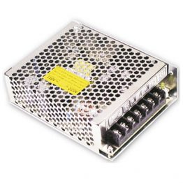
EtherNet/IP Coupler Unit
| Product name | Current consumption | Maximum I/O power supply current | Model |
|---|---|---|---|
EtherNet/IP Coupler Unit |
1.60 W or lower | 10 A | NX-EIC202 |
Automation Software Sysmac Studio
Please purchase a DVD and required number of licenses the first time you purchase the Sysmac Studio. DVDs and licenses are available individually. Each model of licenses does not include any DVD.
| Product name |
Specifications | Model | ||
|---|---|---|---|---|
| Number of licenses |
Media | |||
| Sysmac Studio NX-I/O Edition Ver.1.[][] *1 *2 |
Sysmac Studio NX-I/O Edition is a limited license that provides selected functions required for EtherNet/IP Coupler settings. Because this product is a license only, you need the Sysmac Studio Standard Edition DVD media to install it. |
1 license | — | SYSMAC-NE001L |
| Sysmac Studio Standard Edition Ver.1.[][] *2 |
The Sysmac Studio is the software that provides an integrated environment for setting, programming, debugging and maintenance of machine automation controllers including the NJ/NX-series CPU Units, NY- series Industrial PC, EtherCAT Slave, and the HMI. Sysmac Studio runs on the following OS. This software provides functions of the Vision Edition. |
— (Media only) |
DVD | SYSMAC-SE200D |
(SYSMAC-NE001L).
*2. With the Sysmac Studio Standard Edition with license(s) (SYSMAC-SE[][][]L) version 1.10 or higher, you can use the
setup functions for the EtherNet/IP Coupler.
Connecting Cable
Peripheral (USB) Port
Use a commercially available USB-certified cable.
Specifications: USB 1.1 or 2.0 cable (A connector – B connector), 5.0 m max.
Recommended EtherNet/IP Communications Cables
For EtherNet/IP, required specification for the communications cables varies depending on the baud rate. For 100BASE-TX/10BASE-T, use a straight or cross STP (shielded twisted-pair) cable of category 5 or higher. For 1000BASE-T, use a straight or cross STP cable of category 5e or higher with double shielding (aluminum tape and braiding).
Cable with Connectors
| Item | Appearance | Recommended manufacturer |
Cable length (m) |
Model |
|---|---|---|---|---|
| Cable with Connectors on Both Ends (RJ45/RJ45) Standard RJ45 plugs type *1 Wire Gauge and Number of Pairs: AWG26, 4-pair Cable Cable Sheath material: LSZH *2 Cable color: Yellow *3 |
 |
OMRON | 0.3 | XS6W-6LSZH8SS30CM-Y |
| 0.5 | XS6W-6LSZH8SS50CM-Y | |||
| 1 | XS6W-6LSZH8SS100CM-Y | |||
| 2 | XS6W-6LSZH8SS200CM-Y | |||
| 3 | XS6W-6LSZH8SS300CM-Y | |||
| 5 | XS6W-6LSZH8SS500CM-Y | |||
| Cable with Connectors on Both Ends (RJ45/RJ45) Rugged RJ45 plugs type *1 Wire Gauge and Number of Pairs: AWG22, 2-pair Cable Cable color: Light blue |
 |
OMRON | 0.3 | XS5W-T421-AMD-K |
| 0.5 | XS5W-T421-BMD-K | |||
| 1 | XS5W-T421-CMD-K | |||
| 2 | XS5W-T421-DMD-K | |||
| 5 | XS5W-T421-GMD-K | |||
| 10 | XS5W-T421-JMD-K | |||
| Cable with Connectors on Both Ends (M12 Straight/M12 Straight) Shield Strengthening Connector cable *4 M12/Smartclick Connectors Wire Gauge and Number of Pairs: AWG22, 2-pair Cable Cable color: Black |
 |
OMRON | 0.5 | XS5W-T421-BM2-SS |
| 1 | XS5W-T421-CM2-SS | |||
| 2 | XS5W-T421-DM2-SS | |||
| 3 | XS5W-T421-EM2-SS | |||
| 5 | XS5W-T421-GM2-SS | |||
| 10 | XS5W-T421-JM2-SS | |||
| Cable with Connectors on Both Ends (M12 Straight/RJ45) Shield Strengthening Connector cable *4 M12/Smartclick Connectors Rugged RJ45 plugs type Wire Gauge and Number of Pairs: AWG22, 2-pair Cable Cable color: Black |
 |
OMRON | 0.5 | XS5W-T421-BMC-SS |
| 1 | XS5W-T421-CMC-SS | |||
| 2 | XS5W-T421-DMC-SS | |||
| 3 | XS5W-T421-EMC-SS | |||
| 5 | XS5W-T421-GMC-SS | |||
| 10 | XS5W-T421-JMC-SS |
*1. Standard type cables length 0.2, 0.3, 0.5, 1, 1.5, 2, 3, 5, 7.5, 10, 15 and 20 m are available.
Rugged type cables length 0.3, 0.5, 1, 2, 3, 5, 10 and 15 m are available. For details, refer to Cat.No.G019.
*2. The lineup features Low Smoke Zero Halogen cables for in-cabinet use and PUR cables for out-of-cabinet use.
Although the LSZH cable is single shielded, its communications and noise characteristics meet the standards.
*3. Cables colors are available in blue, yellow, or Green.
*4. For details, contact your OMRON representative.
Cables / Connectors
| Item | Recommended manufacturer |
Model | ||
|---|---|---|---|---|
| Products for EtherNet/IP (100BASE-TX) |
Wire Gauge and Number of Pairs: AWG24, 4-pair Cable |
Cables | Hitachi Cable, Ltd. | NETSTAR-C5E SAB 0.5 × 4P *1 |
| Kuramo Electric Co. | KETH-SB *1 | |||
| SWCC Showa Cable Systems Co. |
FAE-5004 *1 | |||
| RJ45 Connectors | Panduit Corporation | MPS588-C *1 | ||
| Products for EtherNet/IP (100BASE-TX) |
Wire Gauge and Number of Pairs: AWG22, 2-pair Cable |
Cables | Kuramo Electric Co. | KETH-PSB-OMR *2 |
| JMACS Japan Co., Ltd. | PNET/B *2 | |||
| RJ45 Assembly Connector  |
OMRON | XS6G-T421-1 *2 | ||
*1. We recommend you to use above cable for EtherNet/IP and RJ45 Connector together.
*2. We recommend you to use above cable for EtherNet/IP and RJ45 Assembly Connector together.
Optional Products
| Product name | Specification | Model |
|---|---|---|
| Unit/Terminal Block Coding Pins | Pins for 10 Units (30 terminal block pins and 30 Unit pins) | NX-AUX02 |
| Product name | Specification | Model | |||
|---|---|---|---|---|---|
| No. of terminals | Terminal number indications |
Ground terminal mark |
Terminal current capacity |
||
| Terminal Block | 8 | A/B | Provided | 10 A | NX-TBC082 |
General Specification
| Item | Specification | |
|---|---|---|
| Enclosure | Mounted in a panel | |
| Grounding method | Ground to 100 Ω or less | |
| Operating environment |
Ambient operating temperature |
0 to 55°C |
| Ambient operating humidity |
10% to 95% (with no condensation or icing) | |
| Atmosphere | Must be free from corrosive gases. | |
| Ambient storage temperature |
-25 to 70°C (with no condensation or icing) | |
| Altitude | 2,000 m max. | |
| Pollution degree | Pollution degree 2 or less: Conforms to JIS B 3502 and IEC 61131-2. | |
| Noise immunity | Conforms to IEC 61000-4-4. 2 kV (power supply line) | |
| Overvoltage category | Category II: Conforms to JIS B 3502 and IEC 61131-2. | |
| EMC immunity level | Zone B | |
| Vibration resistance | Conforms to IEC 60068-2-6. 5 to 8.4 Hz with 3.5-mm amplitude, 8.4 to 150 Hz, acceleration of 9.8 m/s2, 100 min each in X, Y, and Z directions (10 sweeps of 10 min each = 100 min total) *1 |
|
| Shock resistance | Conforms to IEC 60068-2-27. 147 m/s2, 3 times each in X, Y, and Z directions *1 | |
| Applicable standards *2 | cULus: Listed UL508, ANSI/ISA 12.12.01 EU: EN 61131-2, C-Tick or RCM, KC: KC Registration |
|
specifications of the Relay Output Unit.
*2. Consult your OMRON representative for the most recent applicable standards for each model.
EtherNet/IP Coupler Unit Specifications
| Item | Specification | ||
|---|---|---|---|
| Model | NX-EIC202 | ||
| Number of connectable NX Units |
63 Units max.*1 | ||
| Communications protocols |
EtherNet/IP | ||
| UDP/IP and TCP/IP (Message Services) | Number of buffers (sockets): • 8 message buffers for server • No message buffers for client • Shared buffers for UDP/IP messages and TCP/IP messages Maximum message size: • Request: 492 bytes • Response: 496 bytes Maximum NX output data size: • 490 bytes Maximum NX input data size: • 496 bytes |
||
| Modulation | Baseband | ||
| Link speed | 100 Mbps | ||
| Physical layer | 100BASE-TX (IEEE 802.3) | ||
| Number of connections | 8 | ||
| Received Packet Interval (RPI, refresh cycle) |
4 to 1,000 ms | ||
| Allowed communications bandwidth addressing to the local node |
1,000 pps | ||
| Topology | Line, Tree, Star | ||
| Ethernet Switch | Layer 2 Ethernet switch | ||
| Transmission media | Category 5 or higher twisted-pair cable (Recommended cable: double-shielded cable with aluminum tape and braiding) |
||
| Transmission distance | Distance between nodes: 100 m or less | ||
| NX bus I/O data size | Input: 512 bytes max. (including input data, status, and unused areas) Output: 512 bytes max. (including output data and unused areas) |
||
| EtherNet/IP I/O connection size |
Input: 504 bytes max. (including input data, status, and unused areas) Output: 504 bytes max. (including output data and unused areas) |
||
| Refreshing methods | Free-Run refreshing | ||
| Unit power supply *2 |
Power supply voltage | 24 VDC (20.4 to 28.8 VDC) | |
| NX Unit power supply capacity |
10 W max. (Refer to Installation orientation and restrictions for details.) | ||
| NX Unit power supply efficiency |
70% | ||
| Isolation method | No isolation between NX Unit power supply and Unit power supply terminals | ||
| Current capacity of power supply terminals |
4 A max. | ||
| I/O power supply *2 |
Power supply voltage | 5 to 24 VDC (4.5 to 28.8 VDC) *3 | |
| Maximum I/O power supply current |
10 A (Refer to Installation orientation and restrictions for details.) | ||
| Current capacity of power supply terminals |
10 A max. | ||
| NX Unit power consumption | 1.60 W max. | ||
| Current consumption from I/O power supply |
10 mA max. (for 24 VDC) | ||
| Dielectric strength | 510 VAC for 1 min, leakage current: 5 mA max. (between isolated circuits) | ||
| Insulation resistance | 100 VDC, 20 MΩ min. (between isolated circuits) | ||
| External connection terminals |
Communications Connector For EtherNet/IP communications. • RJ45 × 2 (shielded) |
||
| Screwless Clamping Terminal Block For Unit power supply, I/O power supply, and grounding. Removable. |
|||
| Peripheral USB Port For Sysmac Studio connection. • Physical layer: USB 2.0-compliant, B-type connector • Transmission distance: 5 m max. |
|||
| Dimensions | 46 × 100 × 71 mm (W×H×D) | ||
| Weight | 150 g max. | ||
| Installation orientation and restrictions |
Installation orientation: 6 possible orientations Restrictions: • Used in the upright installation orientation.  • Used in any other orientation than the upright installation orientation.  |
||
| Circuit layout |  |
||
| Terminal arrangement |  |
||
| Accessory | End Cover (NX-END01): 1 | ||
*1. Refer to the NX-series Safety Control Unit User’s Manual (Cat. No. Z930) for the number of Safety Control Units that
can be connected.
*2. Refer to the NX-series EtherNet/IP™Coupler Unit User’s Manual (Cat. No. W536) for procedures for designing the
Unit power supply system and I/O power supply system.
*3. Use a voltage that is appropriate for the I/O circuits of the NX Units and the connected external devices.
Configuration Unit
Refer to the user’s manuals for information on the NX Units that can be connected to the NX-series EtherNet/IP Coupler Unit.
EtherNet/IP Coupler Unit
| Unit | Model |
|---|---|
| EtherNet/IP Coupler Unit | NX-EIC202 |
I/O Units
| Unit | Model | ||||
|---|---|---|---|---|---|
| 2-point Units | 4-point Units | 8-point Units | 16-point Units | 32-point Units | |
| Digital Input Unit | – | NX-ID3317 NX-ID3343 NX-ID3417 NX-ID3443 NX-IA3117 |
NX-ID4342 NX-ID4442 |
NX-ID5142-1 NX-ID5142-5 NX-ID5342 NX-ID5442 |
NX-ID6142-5 NX-ID6142-6 |
| Digital Output Unit | NX-OC2633 NX-OC2733 |
NX-OD3121 NX-OD3153 NX-OD3256 NX-OD3257 NX-OD3268 |
NX-OD4121 NX-OD4256 NX-OC4633 |
NX-OD5121 NX-OD5121-1 NX-OD5121-5 NX-OD5256 NX-OD5256-1 NX-OD5256-5 |
NX-OD6121-5 NX-OD6256-5 |
| Digital Mixed I/O Unit | – | – | – | NX-MD6121-5 NX-MD6121-6 NX-MD6256-5 |
– |
| Analog Input Unit | NX-AD2603 NX-AD2604 NX-AD2608 NX-AD2203 NX-AD2204 NX-AD2208 |
NX-AD3603 NX-AD3604 NX-AD3608 NX-AD3203 NX-AD3204 NX-AD3208 |
NX-AD4603 NX-AD4604 NX-AD4608 NX-AD4203 NX-AD4204 NX-AD4208 |
– | – |
| Analog Output Unit | NX-DA2603 NX-DA2605 NX-DA2203 NX-DA2205 |
NX-DA3603 NX-DA3605 NX-DA3203 NX-DA3205 |
– | – | – |
| Temperature Input Unit | NX-TS2101 NX-TS2102 NX-TS2104 NX-TS2201 NX-TS2202 NX-TS2204 |
NX-TS3101 NX-TS3102 NX-TS3104 NX-TS3201 NX-TS3202 NX-TS3204 |
– | – | – |
| Heater Burnout Detection Unit |
– | NX-HB3101 NX-HB3201 |
– | – | – |
Temperature Control Units
| Unit | Model | |
|---|---|---|
| 2CH | 4CH | |
| Temperature Control Unit | NX-TC2405, NX-TC2406, NX-TC2407, NX-TC2408 |
NX-TC3405, NX-TC3406, NX-TC3407, NX-TC3408 |
Load Cell Input Unit
| Unit | Model |
|---|---|
| Load Cell Input Unit | NX-RS1201 |
Position Interface Units
| Unit | Model | |
|---|---|---|
| 1CH | 2CH | |
| Incremental Encoder Input Unit | NX-EC0112, NX-EC0122, NX-EC0132, NX-EC0142 | NX-EC0212, NX-EC0222 |
| SSI Input Unit | NX-ECS112 | NX-ECS212 |
| Pulse Output Unit | NX-PG0112, NX-PG0122 | – |
Communications Interface Units
| Unit | Model |
|---|---|
| Communications Interface Unit | NX-CIF101, NX-CIF105, NX-CIF210 |
System Units
| Unit | Model |
|---|---|
| Additional NX Unit Power Supply Unit | NX-PD1000 |
| Additional I/O Power Supply Unit | NX-PF0630, NX-PF0730 |
| I/O Power Supply Connection Unit | NX-PC0010, NX-PC0020, NX-PC0030 |
| Shield Connection Unit | NX-TBX01 |
IO-Link Master Unit
| Unit | Model |
|---|---|
| IO-Link Master Unit | NX-ILM400 |
Safety Control Units
| Unit | Model |
|---|---|
| Safety CPU Unit | NX-SL3300 *1 |
| Safety Input Unit | NX-SIH400 *2, NX-SID800 |
| Safety Output Unit | NX-SOH200, NX-SOD400 |
*1 Safety CPU Unit Ver.1.1 or higher.
*2 Safety Input Unit Ver.1.1 or higher.
Version Information
Depending on the type and model of the Unit, some Units do not have all of the versions given in the corresponding versions. If a Unit does not have the specified version, support is provided by the oldest available version after the specified version. Refer to the user’s manuals for the specific Units for the relation between models and versions.
Connection to the NJ/NX-series CPU Unit or NY-series Industrial PC
NX-series CPU Unit or NY-series Industrial PC
| EtherNet/IP Coupler Unit | Corresponding unit version/version | ||||
|---|---|---|---|---|---|
| Model | Unit version | Unit version of CPU Unit or Industrial PC |
Sysmac Studio version |
Network Configurator for EtherNet/IP version |
CX-ConfiguratorFDT version |
| NX-EIC202 | Ver.1.2 | Ver.1.14 | Ver.1.19 | Ver.3.21 | Ver.2.4 * |
| Ver.1.0 | Not possible. | Not possible. | Not possible. | Not possible. | |
EtherNet/IP Coupler Unit.
NJ-series CPU Unit
| EtherNet/IP Coupler Unit | Corresponding unit version/version | |||||
|---|---|---|---|---|---|---|
| Model | Unit version | Unit version of CPU Unit |
Unit version of CJ1W-EIP21 |
Sysmac Studio version |
Network Configurator for EtherNet/IP version |
CX- ConfiguratorFDT version |
| NX-EIC202 | Ver.1.2 | Ver.1.14 | Ver.2.1 | Ver.1.19 | Ver.3.21 | Ver.2.4 * |
| Ver.1.0 | Not possible. | Not possible. | Not possible. | Not possible. | Not possible. | |
EtherNet/IP Coupler Unit.
Connection to CS/CJ/CP-series CPU Unit
CS1G/CS1H/CJ1H/CJ1M CPU Units
| EtherNet/IP Coupler Unit | Corresponding unit version/version | |||||
|---|---|---|---|---|---|---|
| Model | Unit version | Unit version of CPU Unit |
Unit version of CS1W-EIP21/ CJ1W-EIP21 |
Network Configurator for EtherNet/IP version |
NX-IO Configurator version |
CX- ConfiguratorFDT version |
| NX-EIC202 | Ver.1.2 | Ver.3.0 | Ver.2.1 | Ver.3.00 | Ver.1.00 | Ver.2.4 *1 |
| Ver.1.0 | Ver.1.00 *2 | Ver.2.2 | ||||
EtherNet/IP Coupler Unit.
*2. You can connect only to the peripheral USB port on the EtherNet/IP Coupler Unit. You cannot connect with any other
path.
CJ2H-CPU6[]/CJ2M-CPU1[]/CP1H CPU Unit
| EtherNet/IP Coupler Unit | Corresponding unit version/version | |||||
|---|---|---|---|---|---|---|
| Model | Unit version | Unit version of CPU Unit |
Unit version of CJ1W-EIP21 |
Network Configurator for EtherNet/IP version |
NX-IO Configurator version |
CX- ConfiguratorFDT version |
| NX-EIC202 | Ver.1.2 | Ver.1.0 | Ver.2.1 | Ver.3.00 | Ver.1.00 | Ver.2.4 *1 |
| Ver.1.0 | Ver.1.00 *2 | Ver.2.2 | ||||
EtherNet/IP Coupler Unit.
*2. You can connect only to the peripheral USB port on the EtherNet/IP Coupler Unit. You cannot connect with any other
path.
CJ2H-CPU6[]-EIP CPU Unit
| EtherNet/IP Coupler Unit | Corresponding unit version/version | |||||
|---|---|---|---|---|---|---|
| Model | Unit version | Unit version of CPU Unit |
Unit version of CJ1W-EIP21 |
Network Configurator for EtherNet/IP version |
NX-IO Configurator version |
CX- ConfiguratorFDT version |
| NX-EIC202 | Ver.1.2 | Ver.1.5 | Ver.2.1 | Ver.3.00 | Ver.1.00 | Ver.2.4 *1 |
| Ver.1.0 | Ver.1.00 *2 | Ver.2.2 | ||||
EtherNet/IP Coupler Unit.
*2. You can connect only to the peripheral USB port on the EtherNet/IP Coupler Unit. You cannot connect with any other
path.
CJ2M-CPU3[] CPU Unit
| EtherNet/IP Coupler Unit | Corresponding unit version/version | |||||
|---|---|---|---|---|---|---|
| Model | Unit version | Unit version of CPU Unit |
Unit version of CJ1W-EIP21 |
Network Configurator for EtherNet/IP version |
NX-IO Configurator version |
CX- ConfiguratorFDT version |
| NX-EIC202 | Ver.1.2 | Ver.1.0 | Ver.2.1 | Ver.3.21 | Ver.1.00 | Ver.2.4 *1 |
| Ver.1.0 | Ver.1.00 *2 | Ver.2.2 | ||||
EtherNet/IP Coupler Unit.
*2. You can connect only to the peripheral USB port on the EtherNet/IP Coupler Unit. You cannot connect with any other
path.
Connection to the Sysmac Gateway
Sysmac Gateway
| EtherNet/IP Coupler Unit | Corresponding unit version/version | ||||
|---|---|---|---|---|---|
| Model | Unit version | Sysmac Gateway version |
Network Configurator for EtherNet/IP version |
NX-IO Configurator version |
CX- ConfiguratorFDT version |
| NX-EIC202 | Ver.1.2 | Ver.1.31 | Ver.3.50 | Ver.1.00 | Ver.2.4 *1 |
| Ver.1.0 | Ver.1.00 *2 | Ver.2.2 | |||
EtherNet/IP Coupler Unit.
*2. You can connect only to the peripheral USB port on the EtherNet/IP Coupler Unit. You cannot connect with any other
path.
EtherCAT Coupler Unit Only
With Cables Connected
*1. This dimension depends on the specifications of the commercially available USB-certified cable.
Check the specifications of the USB cable that is used.
*2. This is the dimension from the back of the Unit to the communications cables.
• 100 mm: When an MPS588-C Connector is used.
• 120 mm: When an XS6G-T421-1 Connector is used.
End Cover
|
Catalog Name
|
Catalog Number
[size] |
Last Update
|
|---|---|---|
| – [2224KB] |
Aug 01, 2018 | |
| R183-E1-09 [6683KB] |
Nov 01, 2018 |


Reviews
There are no reviews yet.