
Description
Improve Productivity with High-speed Control
• A faster pulse output startup time has been achieved. Pulse output will start as fast as 0.1 ms from when the CPU Unit sends the command. (Previous models started pulse output in 2 ms.)
• Pulse output is possible at up to 4 Mpps for compatibility with linear motors and direct drive motors. This achieves both high resolution and high speed.
Increased Added Value with More Advanced Features
• Operation between the CPU Unit and the Position Control Unit can be synchronized using a high-speed bus. Synchronized control is possible between up to five Units, or 20 axes. A wide range of applications can be achieved by also using the electronic cam function.
• Built-in high-speed counters enable monitoring the present values of the motors while controlling positions, all with just a Position Control Unit. The absolute encoders of G-series and G5-series Servomotors are supported, enabling an absolute positioning system.* This eliminates the need to redefine the origin after power interruptions, helping to provide extra added value.
• Select from direct operation or memory operation. Up to 500 positioning sequences can be saved as the data for memory operation for each axis. Any of three end patterns, independent, automatic, or consecutive, can be set for each sequence, and repeat instructions and jump instructions can be used to achieve complex motion control.
• Linear interpolation, circular interpolation, index table control, feeder control, and an MPG function can be used to achieve the functionality of a Motion Control Unit with these Position Control Units.
• A wide range of functions enables easily achieving position control, including teaching, overrides, backlash compensation, zone settings, and S-curve acceleration/deceleration.
Reduce TCO
• All Support Software functions have been integrated into the CX-Programmer. In combination with data tracing and other CX-Programmer functions, work efficiency is improved from design and debugging to system implementation and maintenance.
• The Position Control Units with line-driver outputs generate the 5-VDC power for the line driver internally. Control is possible by providing only a 24-VDC power supply, in the same way as for Units with open-collector outputs.
• A function block library is being prepared that provides function blocks for all Position Control Unit functions. This will reduce ladder programming work. Even sync applications that use an electronic cam will be easy to construct with the function block library.
* You cannot use an absolute encoder if you use a reduction gear.
International Standards
- The standards are abbreviated as follows: U: UL, U1: UL (Class I Division 2 Products for Hazardous Locations), C: CSA, UC: cULus, UC1: cULus (Class I Division 2 Products for Hazardous Locations), CU: cUL, N: NK, L: Lloyd, and CE: EC Directives.
- Contact your OMRON representative for further details and applicable conditions for these standards.
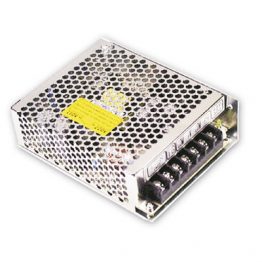
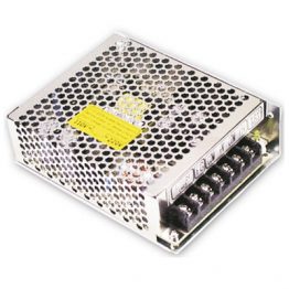
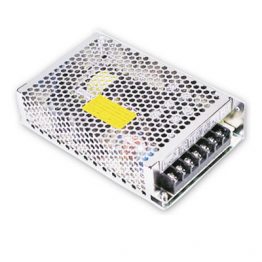
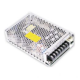
Position Control Units
| Unit type |
Name | Specifications | No. of unit numbers allocated |
Current consumption (A) |
Model | Stand- ards |
||
|---|---|---|---|---|---|---|---|---|
| Control method/ Control output interface |
Number of control axes |
5 V system |
24 V system |
|||||
| CJ1 Special I/O Units |
Position Control Units (High- Speed type) |
Pulse-train open- collector output with Pulse Counter Function |
2 axes | 2 | 0.27 | — | CJ1W-NC214 | UC1, CE |
| 4 axes | 0.31 | — | CJ1W-NC414 | |||||
| Pulse-train line-driver output with Pulse Counter Function |
2 axes | 2 | 0.27 | — | CJ1W-NC234 | |||
| 4 axes | 0.31 | — | CJ1W-NC434 | |||||
Note: This unit cannot be used with the Machine Automation Controller NJ-series.
Support Software
| Product name |
Specifications | Model | Stand- ards |
||
|---|---|---|---|---|---|
| Number of licenses |
Media | ||||
| FA Integrated Tool Package CX-One Ver.4.[] |
The CX-One is a comprehensive software package that integrates Support Software for OMRON PLCs and components. CX-One runs on the following OS. OS: Windows XP (Service Pack 3 or higher, 32-bit version)/Windows Vista (32-bit/64-bit version)/ Windows 7 (32-bit/64-bit version)/Windows 8 (32- bit/64-bit version)/Windows 8.1 (32-bit/64-bit version)/Windows 10 (32-bit/64-bit version) CX-One Ver.4.[] includes CX-Programmer Ver.9.[]. |
1 license * |
DVD | CXONE-AL01D-V4 | — |
* Multi licenses (3, 10, 30, or 50 licenses) and DVD media without licenses are also available for the CX-One.
Connecting Cables
| Applicable Units | Applicable Servo Drive | Number of control axes |
Cable Length |
Model | ||
|---|---|---|---|---|---|---|
| Output Type | Model | Name | Model | |||
| Open-collector output |
CJ1W-NC[]14 | OMNUC G/G5 Series | R88D-GT/-KT | 1 axis | 1m | XW2Z-100J-G13 |
| 3m | XW2Z-300J-G13 | |||||
| SMARTSTEP2 | R7D-BP | 1m | XW2Z-100J-G16 | |||
| 3m | XW2Z-300J-G16 | |||||
| OMNUC G/G5 Series | R88D-GT/-KT | 2 axes | 1m | XW2Z-100J-G5 | ||
| 3m | XW2Z-300J-G5 | |||||
| SMARTSTEP2 | R7D-BP | 1m | XW2Z-100J-G8 | |||
| 3m | XW2Z-300J-G8 | |||||
| Line-driver output |
CJ1W-NC[]34 | OMNUC G/G5 Series | R88D-GT/-KT | 1 axis | 1m | XW2Z-100J-G9 |
| 5m | XW2Z-500J-G9 | |||||
| 10m | XW2Z-10MJ-G9 | |||||
| SMARTSTEP2 | R7D-BP | 1m | XW2Z-100J-G12 | |||
| 5m | XW2Z-500J-G12 | |||||
| 10m | XW2Z-10MJ-G12 | |||||
| OMNUC G/G5 Series | R88D-GT/-KT | 2 axes | 1m | XW2Z-100J-G1 | ||
| 5m | XW2Z-500J-G1 | |||||
| 10m | XW2Z-10MJ-G1 | |||||
| SMARTSTEP2 | R7D-BP | 1m | XW2Z-100J-G4 | |||
| 5m | XW2Z-500J-G4 | |||||
| 10m | XW2Z-10MJ-G4 | |||||
Devices for External Signal Connection
Devices for External Signal Connection
| Name | Specifications | Model |
|---|---|---|
| Connecting Cables for Connector Terminal Block | Cable length: 0.5 m | XW2Z-C50X |
| Cable length: 1.0 m | XW2Z-100X | |
| Cable length: 2.0 m | XW2Z-200X | |
| Cable length: 3.0 m | XW2Z-300X | |
| Cable length: 5.0 m | XW2Z-500X | |
| Cable length: 10.0 m | XW2Z-010X | |
| Connector Terminal Block | 20-points, M2.4 screw terminal | XW2B-20G4 |
| 20-points, M3.5 screw terminal | XW2B-20G5 | |
| 20-points, M3 screw terminal | XW2D-20G6 |
Servo Drive Connector
| Name | Specifications | Model |
|---|---|---|
| Connector Socket | For a 50-pin MIL plug-crimp socket connector For AWG24 |
XG5M-5032-N |
| Connector Cover | For a 50-pin MIL plug-crimp socket connector | XG5S-5022 |
Cables with Crimp Terminals (20 Poles)
| Cable Length | Model |
|---|---|
| 1.0 m | XW2Z-100F |
| 1.5 m | XW2Z-150F |
| 2.0 m | XW2Z-200F |
| 3.0 m | XW2Z-300F |
| 5.0 m | XW2Z-500F |
| 10.0 m | XW2Z-010F |
| 15.0 m | XW2Z-15MF |
| 20.0 m | XW2Z-20MF |
Accessories
MIL Connectors are not included. Use one of the applicable connector or a dedicated cable with connectors listed above.
General Specifications
| Specification item | Model | |
|---|---|---|
| CJ1W-NC214/234 | CJ1W-NC414/434 | |
| Power supply voltage | 5 VDC (unit) | |
| 24 VDC (external power supply) | ||
| Allowable power supply voltage range | 21.6 to 26.4 VDC (external power supply) | |
| Internal current consumption | 5 VDC, 270 mA maximum | 5 VDC, 310 mA maximum |
| Current consumption of external power supply | 24 VDC NC214 13 mA maximum NC234 44 mA maximum |
24 VDC NC414 26 mA maximum NC434 90 mA maximum |
| Dimensions | 90 × 51 × 65 (H × W × D) | 90 × 62 × 65 (H × W × D) |
| Weight | 170 g maximum | 220 g maximum |
| Ambient operating temperature | 0 to 55 °C | |
| Mounting position | CJ-series CPU Rack or CJ-series Expansion Rack | |
| Maximum number of units per rack | 5 units | |
| Maximum number of units per CJ system | 20 units (when up to 3 expansion racks are connected) | |
| Occupied unit | No. 2 | |
| Applicable standards | cULus, EC directives | |
Models other than above conform to the general specifications of the CJ series.
Performance Specifications
| Specification item | Model | ||
|---|---|---|---|
| CJ1W-NC214/234 | CJ1W-NC414/434 | ||
| Applicable PLCs | CJ-series | ||
| Number of occupied inputs/outputs |
Number of words | 18CH * | |
| Controlled drivers | Servo Drive of pulse train input type or stepping motor drivers NC214/414: Open collector output type NC234/434: Line driver output type |
||
| Pulse output method | Phase difference pulse output, forward/reverse direction pulse output, pulse + direction output |
||
| Controls | Control method | Open-loop control by pulse train output | |
| Number of controlled axes |
2 axes | 4 axes | |
| Units of control | Pulse, mm, inch, degree | ||
| Positioning functions | Memory operation, direct operation | ||
| Independent operation | Independent, 2 axes | Independent, 4 axes | |
| Linear interpolation | 2 axes maximum | 4 axes maximum | |
| Circular interpolation | 2 axes maximum | 2 axes maximum | |
| Speed control | Independent, 2 axes | Independent, 4 axes | |
| Interrupt Constant- pitch Feed |
Independent, 2 axes | Independent, 4 axes | |
| Position command |
Data | -2147483648 to +2147483647 | |
| Number of data | 500 per task (4 tasks per unit) | ||
| Speed command |
Data | Position control: 1 to 2147483647 Speed control: -2147483648 to 2147483647 However, this limits the maximum output frequency based on whether the maximum speed is 4 Mpps (NC234/434) or 500 kpps (NC214/414). |
|
| Number of data | 500 per task | ||
| Acceleration/ deceleration time |
Data | 0 to 250000 ms | |
| Number of data | 500 per task | ||
| Function | Override | 0.01% to 500.00% (settable for each axis) | |
| Software limits | – 2147483647 to 2147483646 command unit (Settable for each axis) | ||
| Backlash Compensation | 0 to 50000 command unit (settable for each axis) | ||
| MPG and external encoder counter input |
Number of input words | 1 word (switchable for each controlled axis) | |
| Input interface | Photocoupler input | ||
| Maximum response frequency |
500 kHz | ||
| Feedback pulse counter input |
Number of input words | 4 words (1 word per axis) | |
| Input interface | Line receiver input | ||
| Maximum response frequency |
NC234/434: 4 MHz (phase difference multiplication of 4 times: 1 MHz) NC214/414: 500 kHz (phase difference multiplication of 4 times: 125 kHz) |
||
to up to 144 words according to the number of axes and functions which you use.
Functional Specifications
| Function item | Description | ||
|---|---|---|---|
| Control function |
Single axis control |
Absolute movement | Specify the absolute/relative target position and target speed directly in the ladder program to perform positioning. |
| Relative movement | |||
| Speed control | Specify the target speed directly in the ladder program to perform speed feed. |
||
| Interrupt Feeding | Externally issue an interrupt input during absolute movement, relative movement or speed control to feed the machine by a constant amount to perform positioning. |
||
| Rotational axis control |
Rotational axes suitable for feeder and index table control are supported. In addition to forward/reverse direction positioning, you can also specify short-cut operation. |
||
| Target position and target speed change |
Change the target position or target speed during absolute movement, relative movement or speed control. |
||
| Multi- axis control |
Linear interpolation |
This control starts/ends the operations of multiple axes simultaneously and connects the start position to target position of each axis by a straight line. Linear interpolation of up to 4 axes is possible. |
|
| Circular interpolation |
You can combine 2 desired axes and control each axis in a manner which the axes draw a circular path. Three methods are available to specify a circular arc: “Specification of target position and center point”, “specification of target position, radius and direction” and “target position and passing points”. |
||
| Memory operation |
Automatic operation and continuous operation |
Set the target positions, target speeds and operation patterns in the PCU beforehand to perform a series of operations automatically. Continuous positioning and speed changes are also possible. |
|
| Sequence function | Memory operation data incorporates a sequence feature that allows for repetition of a given operation, start/end of operation data via external inputs, and so on. Accordingly, the PCU can perform various operation sequences without affecting the ladder program of PLC. |
||
| Manual operation function |
Origin Search | This function uses an external sensor, etc. to detect the mechanical origin of the system. You can select a desired origin search operation for your system from 15 different origin search operation patterns. |
|
| Origin Return | This function performs the return operation to the established mechanical origin. |
||
| Present Position Present | It changes the present position to the specified data and establishes the origin. |
||
| Deceleration stop | The operating axis decelerates to a stop. | ||
| JOG Operation | This function feeds the axis in the forward/reverse direction at a constant speed. |
||
| Inching operation | The axis inches in the forward/reverse direction. | ||
| MPG operation | Connect a manual pulsar and perform manual feed. | ||
| Auxiliary control function |
Command unit setting | You can set a desired unit of control for each axis according to the machine. |
|
| Accel- eration/ decel- eration control |
Auto acceleration/ deceleration control |
This function automatically generates an acceleration/deceleration curve for axis operation. You can select the trapezoidal curve or the S-curve based on a tertiary function. |
|
| Acceleration/ deceleration time change |
You can change the acceleration/deceleration time during acceleration/deceleration. |
||
| Acceleration/ deceleration point switch |
You can select one of three methods to connect speeds in different operation patterns during continuous-pattern memory operation. |
||
| Override | This function changes the speed of the axis which is currently in positioning operation. |
||
| Backlash Compensation | This compensates for the mechanical plays to increase the positioning accuracy. |
||
| M code | You can output M codes to implement interlocking with external machines during memory operation. |
||
| Zone setting | You can set a desired zone and assess whether the present position is inside the zone. Up to 3 zones are settable for each axis. |
||
| Feedback pulse counter | A feedback pulse counter input is available for each axis. You can connect encoder pulse outputs from a Servo Drive to monitor deviation from the command position, etc. |
||
| Absolute encoder | You can input encoder pulses from a Servo Drive to a feedback pulse counter to use a motor with absolute encoder. This function supports OMRON G-series and G5-series Servomotors with absolute encoder. |
||
| Teaching | This function enables loading of the present position into memory operation position data. It supports not only the present command position, but also the present position from the feedback pulse counter. |
||
| Torque limit output | An output signal is available for operating the torque limit switch input of a Servo Drive. You can turn this output signal ON/OFF directly in the ladder program. Also, Origin Search by holding supports automatic switching of torque limits. |
||
| Monitor function |
Software limits | You can set forward/reverse direction software limits of axis operation. If the positioning target exceeds software limit, it is detectable at the start through a command value check. |
|
| Position or speed error monitor |
The PCU can monitor the position or speed error between the present command position and present feedback position to generate an error and stop the axis operation upon detection of an excessive error. |
||
| Error between axes monitor |
It can also monitor the error between axes during linear interpolation to generate an error and stop the axes operation upon detection of an excessive error. |
||
(Unit: mm)
Position Control Unit (High-Speed type)
CJ1W-NC214/-NC234
(2-axis control)
![CJ1W-NC[][]4 Dimensions 2](http://www.ia.omron.com/Images/2051_dm_113-108897.gif)
CJ1W-NC414/-NC434
(4-axis control)
![CJ1W-NC[][]4 Dimensions 3](http://www.ia.omron.com/Images/2051_dm_213-108899.gif)
|
Catalog Name
|
Catalog Number
[size] |
Last Update
|
|---|---|---|
| – [2182KB] |
May 19, 2016 |


Reviews
There are no reviews yet.