
Description
• Two types to choose from: open collector output and line driver. Because both open collector output and line driver types feature 1-, 2-, and 4-axis models, the most appropriate model can be selected for the application at hand.
• Positioning START occurs within 2 ms (maximum speed) after receiving a command from the Programmable Controller.
• High-speed data transfer is possible using INTELLIGENT I/O WRITE (IOWR) and INTELLIGENT I/O READ (IORD) instructions.
• Fine control from low to high speed (500 kpps max.) is possible in 1-pps units.
• Positioning can be done from memory, by writing an operating pattern into the PCU memory in advance. Three position patterns − Terminating, Automatic, and Continuous − can be set with completion codes to respond to a wide range of operations. Positioning of up to 100 patterns (sequential data) per one axis can be possible.
• Positioning (direct operation) can be done by direct PLC ladder commands for position data, speed data, and acceleration data. This simplifies control in situations when the target position and speed cannot be decided until immediately before operation begins, or when the target position and speed change due to other circumstances. The target position and speed can also be changed during operation.
• Interrupt feeding moves the axis a specified amount, then stops it, in accordance with an interrupt input. High-speed (0.1 ms max.) processing of the interrupt input signal ensures high-precision interrupt positioning. This helps to maximize feeder precision.
• Easy-to-Use positioning can be possible with versatile functions such as Teaching, Override, Backlash compensation, Zones, Forced interrupt and Acceleration/Deceleration curve.
International Standards
- The standards are abbreviated as follows: U: UL, U1: UL(Class I Division 2 Products for Hazardous Locations), C: CSA, UC: cULus, UC1: cULus (Class I Division 2 Products for Hazardous Locations), CU: cUL, N: NK, L: Lloyd, and CE: EC Directives.
- Contact your OMRON representative for further details and applicable conditions for these standards.
Position Control Unit
| Unit type |
Name | Specifications | No. of unit numbers allocated |
Current consumption (A) |
Model | Standards | ||
|---|---|---|---|---|---|---|---|---|
| Control method/ Control output interface |
Number of control axes |
5 V system |
24 V system |
|||||
| CJ1 Special I/O Units |
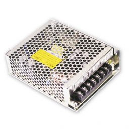
Position control unit  |
Open-loop control by pulse train output/Open- collector output |
1 axis | 1 | 0.25 | — | CJ1W-NC113 | UC1, CE |
| 2 axes | 0.25 | — | CJ1W-NC213 | |||||
| 4 axes * | 2 | 0.36 | — | CJ1W-NC413 | ||||
| Open-loop control by pulse train output/Line-driver output |
1 axis | 1 | 0.25 | — | CJ1W-NC133 | |||
| 2 axes | 0.25 | — | CJ1W-NC233 | |||||
| 4 axes * | 2 | 0.36 | — | CJ1W-NC433 | ||||
| Space Unit |
The ambient operation temperature range can be increased to 0 to 55 °C if the CJ1W-SP001 CJ-series Space Unit is used. |
CJ1W-SP001 | UC1, CE | |||||
* The ambient operating temperature of the CJ1W-NC413/NC433 is 0 to 50°C. Allowable power supply voltage range for
external power supply is 22.8 to 25.2 V DC.
Software
| Name | Specifications | Number of licenses |
Model | Stand- ards |
|---|---|---|---|---|
| FA Integrated Tool Package CX-One Ver.4.[] |
The CX-One is a comprehensive software package that integrates Support Software for OMRON PLCs and components. CX-One runs on the following OS. OS: Windows XP (Service Pack 3 or higher, 32-bit version)/Windows Vista (32-bit/64-bit version)/ Windows 7 (32-bit/64-bit version)/Windows 8 (32- bit/64-bit version)/Windows 8.1 (32-bit/64-bit version)/Windows 10 (32-bit/64-bit version)CX-One Ver.4. [] includes CX-Position Ver.2. []. For details, refer to the CX-One catalog (Cat. No. R134). |
1 license * DVD |
CXONE-AL01D-V4 | — |
* Multi licenses (3, 10, 30, or 50 licenses) and DVD media without licenses are also available for the CX-One.
Servo Relay Unit/Cables
| Name | Applicable units | Applicable drives | Number of control axes |
Cable length |
Model | Stand- ards |
|
|---|---|---|---|---|---|---|---|
| Servo Relay Unit |
For CJ1W-NC113/133 (No communication supported) |
— | 1 axis | — | XW2B-20J6-1B | — | |
| For CJ1W-NC213/233/413/433 (No communication supported) |
— | 2 axes | — | XW2B-40J6-2B | |||
| For CJ1W-NC113/133/213/ 233/413/433 (Communication supported) |
— | 2 axes | — | XW2B-40J6-4A | |||
| Position Control Unit Cables for Servo Relay Unit |
Open- collector output |
For CJ1W-NC113 | OMNUC G/G5 Series, SMARTSTEP 2 |
1 axis | 0.5m | XW2Z-050J-A14 | — |
| 1m | XW2Z-100J-A14 | ||||||
| SMARTSTEP Junior Series |
0.5m | XW2Z-050J-A16 | |||||
| 1m | XW2Z-100J-A16 | ||||||
| For CJ1W- NC213/413 |
OMNUC G/G5 Series, SMARTSTEP 2 |
2 axes | 0.5m | XW2Z-050J-A15 | |||
| 1m | XW2Z-100J-A15 | ||||||
| SMARTSTEP Junior Series |
0.5m | XW2Z-050J-A17 | |||||
| 1m | XW2Z-100J-A17 | ||||||
| Line- driver output |
For CJ1W-NC313 | OMNUC G/G5 Series, SMARTSTEP 2 |
1 axis | 0.5m | XW2Z-050J-A18 | ||
| 1m | XW2Z-100J-A18 | ||||||
| SMARTSTEP Junior Series |
0.5m | XW2Z-050J-A20 | |||||
| 1m | XW2Z-100J-A20 | ||||||
| For CJ1W- NC233/413 |
OMNUC G/G5 Series, SMARTSTEP 2 |
2 axes | 0.5m | XW2Z-050J-A19 | |||
| 1m | XW2Z-100J-A19 | ||||||
| SMARTSTEP Junior Series |
0.5m | XW2Z-050J-A21 | |||||
| 1m | XW2Z-100J-A21 | ||||||
Accessories
The Position Control Unit includes the 40-pin solder-type connectors C500-CE404 (socket: Fujitsu FCN-361J040-AU, cover: Fujitsu FCN-360C040-J2).
Applicable Connectors
| Name | Specifications | Model | |
|---|---|---|---|
| External I/O Connectors |
 |
40 pin, soldered, right angle w/cover (included with the Unit) | C500-CE404 |
| 40 pin, crimped right angle w/cover | C500-CE405 | ||
 |
40 pin, Pressure welded, w/o cover | C500-CE403 | |
 |
40 pin, soldered, w/cover | C500-CE401 | |
| 40 pin, crimped w/cover | C500-CE402 | ||
Basic Specifications
| Item | Model | ||
|---|---|---|---|
| CJ1W-NC113/133 | CJ1W-NC213/233 | CJ1W-NC413/433 | |
| Power supply voltage |
5 V DC (for the PCU itself) | ||
| 24 V DC (external power supply) | |||
| 5 V DC (external power supply; line driver output only) | |||
| Allowable power supply voltage range |
4.75 to 5.25 V DC (for the PCU itself) | ||
| 21.6 to 26.4 V DC (external power supply) | 22.8 to 25.2 V DC (external power supply) |
||
| 4.75 to 5.25 V DC (external power supply; line driver output only) | |||
| Internal current consumption |
250 mA max. at 5 V DC | 250 mA max. at 5 V DC | 360 mA max. at 5 V DC |
| Current consumption of external power supply |
NC113: 30 mA max. at 24 V DC NC133: 10 mA max. at 24 V DC NC133: 60 mA max. at 5 V DC |
NC213: 50 mA max. at 24 V DC NC233: 20 mA max. at 24 V DC NC233: 120 mA max. at 5 V DC |
NC413: 100 mA max. at 24 V DC NC433: 30 mA max. at 24 V DC NC433: 230 mA max. at 5 V DC |
| External dimensions |
90 (H) × 31 (W) × 65 (D) (all models) | ||
| Weight | 100 g max. | 100 g max. | 150 g max. |
| Ambient operating temperature |
0 to 55 ° C | 0 to 50 ° C * | |
* Refer to Operation Manual 3-3-5 Mounting Precaution for CJ1W-NC413/NC433 for information on the ambient operating
temperature of the CJ1W-NC413/433.
Performance Specifications
| Item | Model | |||
|---|---|---|---|---|
| CJ1W-NC113/133 | CJ1W-NC213/233 | CJ1W-NC413/433 | ||
| Applicable PLC models | CJ-series PLCs *1 | |||
| Unit type | Special I/O Unit | |||
| I/O requirements | Words | 5 words | 10 words | 20 words |
| Controlled driver | Pulse-train input-type Servo Drive or stepping motor driver NC113/213/413 models have open collector output. NC133/233/433 models have line driver output. |
|||
| Control | Control system | Open-loop control by pulse train output | ||
| Number of control axes |
1 axis | 2 axes | 4 axes | |
| Control unit | Pulse | |||
| Positioning operations | Two types: memory operation and direct operation | |||
| Positioning operations |
Independent | 1 axis | 2 independent axes | 4 independent axes |
| Linear interpolation | None | 2 axes max. | 4 axes max. | |
| Speed control | 1 axis | 2 independent axes | 4 independent axes | |
| Interrupt feeding | 1 axis | 2 independent axes | 4 independent axes | |
| Positions | Range | -1,073,741,823 to 1,073,741,823 pulses *2 | ||
| Data items | 100/axis | |||
| Speeds | Range | 1 pps to 500 kpps | ||
| Data items | 100/axis | |||
| Acceleration and deceleration times |
Range | 0 to 250 s, until maximum speed is reached. | ||
| Data items | 9/axis for acceleration and deceleration each | |||
| Functions and settings |
Origin search | Origin proximity input signal: selectable (absent, N.O. or N.C. contact). Origin input signal: selectable (N.O. or N.C. contact) Origin compensation: -1,073,741,823 to 1,073,741,823 pulses Origin search speed: High-speed or proximity-speed can be set. Origin detection method: May be set to stop upon origin input signal after proximity input signal has turned ON, to stop upon origin input signal after proximity input signal has turned OFF, to stop upon origin input signal without using proximity input signal, or to stop upon origin input signal after limit input signal has turned OFF. N.O. = Normally open N.C. = Normally closed |
||
| Jogging | Jogging can be executed at a specified speed. | |||
| Dwell times | 19/axis can be set from 0 to 9.99 s (unit: 0.01 s). | |||
| Acceleration/ deceleration curves |
Trapezoidal or S-curve (Can be set separately for each axis.) | |||
| Zones | Zone Flag turns ON when present position is within a specified zone. Three zones can be set for each axis. |
|||
| Software limits | Can be set within a range of -1,073,741,823 to 1,073,741,823 pulses. | |||
| Backlash compensation |
0 to 9,999 pulses. Compensation speed can also be set. | |||
| Teaching | With a command from the PLC, the present position can be taken as the position data. | |||
| Deceleration stop | The STOP command causes positioning to decelerate to a stop according to the specified deceleration time. |
|||
| Emergency stop | Pulse outputs are stopped by an external emergency stop command. | |||
| Present position preset |
The PRESENT POSITION PRESET command can be used to change the present position to a specified value. |
|||
| Override | When the override enabling command is executed during positioning, the target speed is changed by applying the override coefficient. Possible to set to a value from 1 to 999% (by an increment of 1%) |
|||
| Data saving | 1) Saving to flash memory. (Can be written 100,000 times.) 2) Reading from PLC area by data reading instruction. 3) Reading by Support Software and saving to personal computer hard disk or floppy disk. |
|||
| External I/O | Inputs | Prepare the following inputs for each axis: CW and CCW limit input signals, origin proximity input signal, origin input signal, emergency stop input signal, positioning completed signal, interrupt input signal |
||
| Outputs | Prepare the following outputs for each axis: Pulse outputs CW/CCW pulses, pulse outputs and direction outputs can be switched. Either error counter reset or origin-adjustment command outputs can be selected depending on the mode. |
|||
| Pulse output distribution period | 1-axis operation: 4 ms Linear interpolation: 8 ms |
|||
| Response time | Refer to Operation manual Appendix A Performance Characteristics. | |||
| Self-diagnostic function | Flash memory check, memory loss check, CPU bus check | |||
| Error detection function | Overtravel, CPU error, software limit over, emergency stop | |||
CJ1M CPU Unit (either CPU Unit Ver. 2.0 or Pre-Ver. 2.0 CPU Unit). These functions cannot be used if the PCU is
installed with a CJ1 CPU Unit.
*2. When performing linear interpolation, the distances that can be moved will vary.
(Unit: mm)
CJ1W-NC113/213/413
CJ1W-NC133/233/433
![CJ1W-NC[][]3 Dimensions 1](http://www.ia.omron.com/Images/cj1w-nc_dm_113-104610.gif)
CJ1W-SP001
![CJ1W-NC[][]3 Dimensions 2](http://www.ia.omron.com/Images/cj1w-nc_dm_213-104611.gif)
|
Catalog Name
|
Catalog Number
[size] |
Last Update
|
|---|---|---|
| – [2673KB] |
May 12, 2016 |


Reviews
There are no reviews yet.