
Description
Global Standard
Highly Open Global Standard for FA Industry with High Future Potential
The ODVA promotes the spread of Industrial Ethernet all over the world.
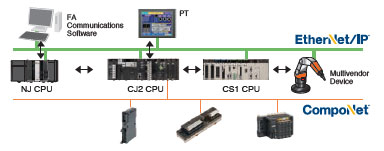
EtherNet/IP can be used to communicate with many devices from various companies around the world in addition to OMRON components (such as Temperature Controllers and Sensors). The use of EtherNet/IP will rapidly increase the development of an EtherNet/IP multivendor environment (including robots and safety devices).
Integrated Information and Control Network
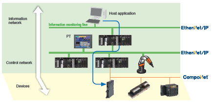
Seamless communications on the control line and information monitoring line with EtherNet/IP
Using the global standard open protocol (CIP), an independent network system can be created with seamless data flow between the control line and the information monitoring line.
OMRON FINS message communications can also be used on the same network because it is a standard LAN.
Improved operation efficiency with common Support Software operation
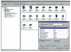
Use the same operating procedures for both EtherNet/IP and DeviceNet Support Software.
The same Support Software procedures can be used from a remote location for device configuration, monitoring, and program transfer for the DeviceNet and EtherNet/IP networks.
Monitor Safety Systems
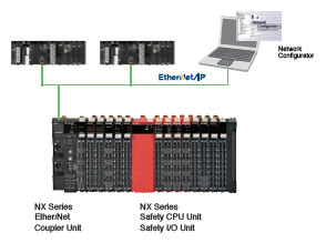
Safety systems can be monitored through the EtherNet/IP.
The safety system can be monitored from a PLC by using a modular designed Safety Control Unit with a EtherNet/IP Coupler Unit.
Convenience of the Universal Ethernet Right in Your Hands
Higher Data Link Capacity (9 times the capacity of previous OMRON models)
High-capacity communications with high-speed high-capacity bus
All types of data, from process interlocks and manufacturing recipes to production data, can be exchanged at high speed and with optimal timing. The ability to communicate is incomparably better than previous networks, such as the Controller Link and FL-net.
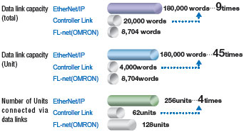
Note: Using a built-in EtherNet/IP port on CJ2H and EtherNet/IP Units.
Low Cost Expansion for Each Line
Flexible topology with the Ethernet switch
Flexible wiring and expansion are possible with Ethernet switches. This means that there will be no total network crashes caused by communications path errors, ensuring high network performance and security.
– Joining and leaving the network is possible during communications.
Nodes can leave the network during operation, enabling easy maintenance for error detection, separation, and restoration.
– Unpredictable delays caused by data collisions are minimum.
– Problems caused by wiring errors are minimized to each line.
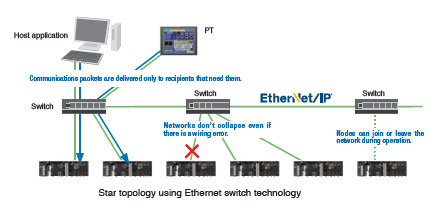
Star topology using Ethernet switch technology
Reduced Network Facility and Wiring Costs
Generic LAN cables can be used.
– Metal cables of category 5, 5e, or higher can be used as LAN cables.
– Generic RJ-45 connectors can be used.
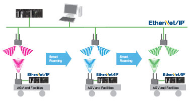
Standard wireless LAN can be used because EtherNet/IP is also Universal Ethernet.
There is no need to rewire even when layout has been changed.
– High-speed Smart Roaming communications can be used for mobile units with the WE70 FA Wireless LAN. The
communications range can be expanded by relaying communications between access points.
Integration of Control and Information Networks
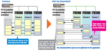
High-speed Data Links with Optimal Cycles for Applications (30 times higher than previous OMRON models)
Flexible and high-speed cyclic communications
Data link table can be divided into up to 256 groups (= connections).
The optimum communications cycle for the application can be set for each group.
– Cyclic synchronization can be set for each group.
The communications cycle can be set to between 0.5 ms and 10 s in 0.5-ms increments. Data concurrency is
maintained for each connection. The communications cycle does not change even if the number of nodes increases.
The communications performance is 30 times better than that of the Controller Link.
Example:
Data link refresh cycle for 25 linked Unit and 20,000 words/network is reduced from 300 ms to 10 ms.
– Facilities can be easily expanded.
When expanding facilities, all you need to do is make additions to the tables. Expansion is possible with little time and
low cost.
Note: Using a built-in EtherNet/IP port on CJ2H and EtherNet/IP Units.
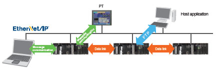
FTP, Data Links, and Support Software Can Be Used Simultaneously with One Port
With the multipurpose EtherNet/IP port, an Ethernet Unit is not required for expansion.
Using the multipurpose EtherNet/IP port built into a CJ/NJ/NX/NY CPU Unit, a single port can be used for data link communications between PLCs, messages between PLCs, and Universal Ethernet communications, such as FTP transfers while connecting Support Software. An EtherNet/IP Unit can be added to any CS/CJ-series PLC to achieve the same functions.

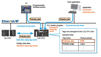
Memory Map Management Becomes Unnecessary.
Freed from memory map by tags
The efficiency of design, startup, maintenance, and upgrading are improved.
– PT and host applications can be developed in parallel.
Network symbols defined in CJ/NJ/NX/NY CPU Units can be used as tags when designing the PT screen.
Design is easy: Just decide on the tag names for the information and control departments.
Changes to allocated addresses is not needed later in development.
– Easier facility upgrading and maintenance
Even if physical addresses change in the PLC, there is no need to make any changes in the data link settings, in the
PT, or in the host application.
International Standards
- The standards are abbreviated as follows: U: UL, U1: UL (Class I Division 2 Products for Hazardous Locations), C: CSA, UC: cULus, UC1: cULus (Class I Division 2 Products for Hazardous Locations), CU: cUL, N: NK, L: Lloyd, and CE: EC Directives.
- Contact your OMRON representative for further details and applicable conditions for these standards.
EtherNet/IP Unit
| Unit type |
Product name |
Specifications | Current consump- tion (A) |
Model | Stand- ards |
||||
|---|---|---|---|---|---|---|---|---|---|
| Communi- cations cable |
Communi- cations functions |
Units per CPU Unit |
No. of unit numbers allocated |
5 V sys- tem |
24 V sys- tem |
||||
| CJ1 CPU Bus Unit |
EtherNet/IP Unit  |
Shielded twisted- pair (STP) cable Categories: 100 Ω at 5, 5e |
Tag Data Link Functions, Message Communications Functions |
8 max. *1 |
1 | 0.41 | — | CJ1W-EIP21 *2 |
UC1, N, L, CE |
a CJ2H-CPU6[]-EIP. Up to two EtherNet/IP Units can be connected to a CJ2M CPU Unit.
*2. EtherNet/IP Unit with unit version 2.1 or later is required to connect C1JW-EIP21 to NJ-series CPU Unit. Use CPU Unit
with version 1.01 or later and Sysmac Studio with version 1.02 or later.
Industrial Switching Hubs
| Product name |
Appearance | Specifications | Accessories | Current con- sump- tion (A) |
Model | Stand- ards |
||
|---|---|---|---|---|---|---|---|---|
| Functions | No. of ports |
Failure detec- tion |
||||||
| Industrial Switching Hubs |
 |
Quality of Service (QoS): EtherNet/IP control data priority Failure detection: Broadcast storm and LSI error detection 10/100BASE-TX, Auto-Negotiation |
3 | No | Power supply connector |
0.22 | W4S1-03B | UC, CE |
 |
5 | No | 0.22 | W4S1-05B | ||||
| 5 | Yes | Power supply connector Connector for informing error |
0.22 | W4S1-05C | CE | |||
EtherNet/IP Units Specifications
| Item | Specifications | |
|---|---|---|
| Model number | CJ1W-EIP21 | |
| Type | 100Base-TX *1 | |
| Applicable PLCs | NJ-series, CJ (CJ1, CJ2) series, CP1H, and NSJ series PLCs. | |
| Unit classification | CJ-series CPU Bus Unit | |
| Mounting location | CPU Rack or Expansion Rack | |
| Number of Units that can be mounted |
NJ-series System: 4 max. (including Expansion Racks) CJ series System and NSJ series System: 8 max. (including Expansion Racks) *2 CP1H System: 2 max. |
|
| CPU Unit words used |
Allocated CIO Area words (CPU Bus Unit words) |
25 words/Unit (one unit number’s words) |
| These words contain control bits and flags, the target node PLC’s operating and error information, Unit status, communications status, registered/normal target node information, and FINS/TCP connection status. |
||
| Allocated DM Area words (CPU Bus Unit words) |
100 words/Unit (one unit number’s words) | |
| These words contain the IP address display/setting area. | ||
| User-set area | Any usable data area words | |
| Target node PLC’s operating and error information, and registered/normal target node information |
||
| CPU Bus Unit System Setup |
Not used. | |
| Non-volatile memory within EtherNet/IP Unit (See note.) |
The following settings are stored in the EtherNet/IP Unit’s non-volatile memory. Note: Unlike the regular Ethernet Units, the CPU Bus Unit Setup Area in the CPU Unit is not used for these settings. 1. Unit Setup (communications settings for the EtherNet/IP Unit, such as the IP address, DNS server settings, host name, baud rate, FINS/UDP settings, and FINS/ TCP settings) 2. Tag data link settings (device parameters) |
|
| Transfer specifi- cations |
Media access method |
CSMA/CD |
| Modulation method | Baseband | |
| Transmission paths | Star form | |
| Baud rate | 100 Mbit/s (100Base-TX) | |
| Transmission media | Shielded twisted-pair (STP) cable Categories: 100 Ω at 5, 5e |
|
| Transmission distance |
100 m (distance between hub and node) | |
| Number of cascade connections |
There is no limitation when a switching hub is used. | |
| Current consumption (Unit) | 410 mA max. at 5 V DC | |
| Weight | 94 g max. | |
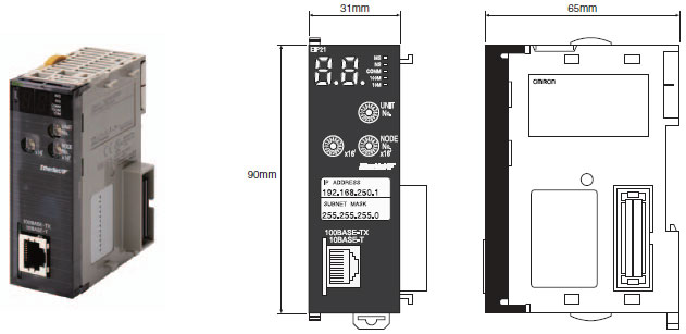
| Dimensions | 31 × 90 × 65 mm (W × H × D) | |
| Other general specifications | Other specifications conform to the general specifications of the CJ-series. | |
*2. Up to seven EtherNet/IP Units can be connected to a CJ2H-CPU6[]-EIP. Up to two EtherNet/IP Units can be connected
to a CJ2M CPU Unit.
Communications Specifications
| Item | Specifications | ||||
|---|---|---|---|---|---|
| NJ | CJ2 | CJ1 | |||
| CIP service |
Tag data links (Cyclic communi- cations) |
Number of connections | 256 | ||
| Packet interval (refresh cycle) |
0.5 to 10,000 ms (in 0.5-ms units) Can be set independently for each connection. (Data is refreshed over the network at the preset interval and does not depend on the number of nodes.) |
||||
| Maximum allowed communications bandwidth per Unit |
6,000 to 12,000 pps *1 *2 | ||||
| Number of tag sets | 256 | ||||
| Tag types | CIO Area, DM Area, EM Area, Holding Area, Work Area, and network symbols *3 |
||||
| Number of tags per connection (= 1 tag set) |
8 (7 tags when the tag set contains the controller status) | ||||
| Maximum link data size per node |
184,832 words | ||||
| Maximum data size per connection *4 |
504 bytes (252 words) or 1444 bytes (722 words) *3 Data synchronicity is maintained within each connection. |
||||
| Number of registrable tag sets |
256 (1 connection = 1 tag set) | ||||
| Maximum size of 1 tag set |
722 words (The controller status uses 1 word when the tag set contains the PLC status.) |
||||
| Maximum number of tags that can be refreshed per CPU Unit cycle *5 |
Output/Transmission (CPU to EtherNet/IP): 256 Input/Reception (EtherNet/IP to CPU): 256 |
Output/Transmission (CPU to EtherNet/IP): 19 Input/Reception (EtherNet/IP to CPU): 20 *6 |
|||
| Data that can be refreshed per CPU Unit cycle *5 |
Output/Transmission (CPU to EtherNet/IP): 6,432 words Input/Reception (EtherNet/IP to CPU): 6,432 words |
Output/Transmission (CPU to EtherNet/IP): 7,405 words Input/Reception (EtherNet/IP to CPU): 7,405 words |
|||
| Changing tag data link parameters during operation |
Supported *7 | ||||
| Multicast packet filter function *8 |
Supported | ||||
| Explicit messaging *9 |
Class 3 (connected) | Number of connections: 128 | |||
| UCMM (unconnected) | Number of clients that can communicate at one time: 32 max. Number of servers that can communicate at one time: 32 max. |
||||
| CIP routing *10 | Supported CJ1W-EIP21, CS1W-EIP21, NJ-501-[][][][], NJ-301-[][][][], CJ2H-CPU[][]-EIP, CJ2M-CPU3[] |
||||
| FINS service | FINS/UDP | Not supported | Supported | ||
| FINS/TCP | Not supported | 16 connections max. | |||
| EtherNet/IP conformance test | Conforms to A8 | ||||
| Ethernet interface | 10BASE-T or 100BASE-TX Auto Negotiation or fixed settings |
||||
*1. In this case, pps means “packets per second” and indicates the number of packets that can be processed in one
second.
*2. When using the EtherNet/IP Unit with version 3.0 or later. When using the EtherNet/IP Unit with version
2.1 or earlier, the maximum allowed communications bandwidth per Unit is 6,000 pps. When using the EtherNet/IP
Unit with version 3.0 or later, the Network Configurator with version 3.57 or higher is required.
*3. Network symbols can be used only by the NJ501-[][][][], NJ301-[][][][], CJ2H-CPU6[]-EIP and CJ2M-CPU3[].
*4. To use 505 to 1,444 bytes as the data size, the system must support the Large Forward Open standard (an optional
CIP specification). The CS/CJ-series Units support this standard, but before connecting to nodes of other companies,
confirm that those devices also support it.
*5. If the maximum data size is exceeded, the data refreshing with the CPU Unit will extend over two or more cycles.
*6. If status layout is selected in the user settings, the maximum number of tags that can be received is 19 tags.
*7. If parameters are changed in the EtherNet/IP Unit, however, the EtherNet/IP Unit will be restarted. When other nodes
are communicating with the affected node, the communications will temporarily time out and automatically recover
later.
*8. Because the EtherNet/IP Unit is equipped with an IGMP client, unnecessary multicast packets can be filtered by using
a switching hub that supports IGMP snooping.
*9. The EtherNet/IP Unit uses the TCP/UDP port numbers shown in the following table.
| Service | Protocol | Port number | Remarks | |||
|---|---|---|---|---|---|---|
| CJ1/CJ2 | NJ | CJ1/CJ2 | NJ | CJ1/CJ2 | NJ | |
| Used by system | — | UDP | — | 2223, 2224 | Fixed value | |
| Tag data links | UDP | 2222 | ||||
| Class3, UCMM | TCP/UDP | 44818 | ||||
| DNS | UDP | 53 | ||||
| BOOTP client | — | UDP | — | 68 | ||
| FINS/UDP service | UDP | — | 9600 | — | Port numbers in the Unit Setup can be changed with the CX-Programmer. |
Port numbers in the Unit Setup can be changed with the Sysmac Studio. |
| FINS/TCP service | TCP | — | 9600 | — | ||
| FTP | TCP | 20, 21 | 21 | |||
| SNTP | UDP | 123 | ||||
| SNMP | UDP | 161 | ||||
| SNMP trap | UDP | 162 | ||||
*10.When NJ-Series CPU Units is described, Supported only by the EtherNet/IP Units with unit version 2.1 or later and
NJ-Series CPU Units with unit version 1.01 or later.
Unit Versions and Software Versions
The following versions of the Sysmac Studio, CX-Programmer and Network Configurator are required to set EtherNet/IP Units.
Yes: Supported, —: Not supported
| CJ1W-EIP21 | Sysmac Studio *1 | CX-Programmer *2 | Network Configurator for EtherNet/IP | ||||
|---|---|---|---|---|---|---|---|
| Ver.1.01 or lower |
Ver.1.02 or higher |
Ver.7.1 or lower |
Ver.8.0 or higher |
Ver.8.02 or higher |
Ver.3.40 or lower | Ver.3.50 or higher | |
| Ver.1.0 | — | — | — | Yes *3 | Yes | Yes | Yes |
| Ver.2.0 | — | — | — | Yes | Yes | Yes | Yes |
| Ver.2.1 | — | Yes | — | Yes | Yes | — | Yes |
| Ver.3.0 *4 | — | Yes | — | Yes | Yes | — | Yes |
*1. Available only when connecting with NJ-series CPU Units.
*2. Available only when connecting with CJ1/CJ2-series CPU Units.
*3. The most recent version of the common module for CX-One version 3.[][] must be installed.
*4. Using the Sysmac Studio auto-update (November 2014 or later).
Network Configurator Requirements
The Network Configurator Ver. 3.0 or higher is a software package designed for building, setting, and controlling a multi-vendor EtherNet/IP Network using OMRON’s EtherNet/IP. It is included in CX-One version 3.0. The Network Configurator provides the following functions for building, setting, and controlling EtherNet/IP.
| Item | Specification | |||
|---|---|---|---|---|
| Operating environment | Refer to the CX-One Setup Manual (Cat. No. W463). CXONE-AL[][]D-V[] |
|||
| Network connection method |
CS1/CJ1 | CJ2 | NJ | |
| Serial interface | CPU Unit’s Peripheral or RS-232C port |
CPU Unit’s USB or RS-232C port | CPU Unit’s USB port | |
| Ethernet interface |
EtherNet/IP Unit’s Ethernet port |
CPU Unit’s Ethernet port EtherNet/IP Unit’s Ethernet port |
||
| Location on Network | A single node address is used (only when directly connected to EtherNet/IP). | |||
| Number of Units that can be connected to Network |
A single Network Configurator per Network (More than one Configurator cannot be used in the same system.) |
|||
| Main functions |
Network control functions |
The Network configuration can be created and edited regardless of whether the Network Configurator is online or offline. The Network configuration can be read from a file or the network. |
||
| Configuration functions |
The EDS files used by the Network Configurator can be installed and deleted. | |||
| Supported file formats | Configurator network configuration files (*.ncf) Configuration files (*.ncf) created using the Network Configurator for EtherNet/IP (version 2) can be imported by selecting External Data – Import from the File Menu. |
|||
(Unit: mm)
CJ1W-EIP21
|
Catalog Name
|
Catalog Number
[size] |
Last Update
|
|---|---|---|
| – [868KB] |
May 09, 2016 | |
| R150-E1-16 [2968KB] |
Sep 03, 2018 |


Reviews
There are no reviews yet.