
Description
• Large-capacity data links are easily achieved without programming simply by setting data link tables.
• Up to 20,000 *1 send/receive words can be set per node for Units (up to 62,000 words for Boards).
• Data links can be performed with up to 4,000 *2 words per node while ensuring data concurrency.
• User-set data link tables can be changed while data links are operating. *3
• Errors for the entire system can be monitored by using error diagnosis support software and a variety of status flags.
• With the token ring mode of Optical Ring Controller Link Units/Boards, duplex communications paths enable communications to continue normally even if the cable becomes disconnected.
• Detecting locations of disconnection greatly shortens time required for maintenance.
• Installing Controller Link Units in a CS1D system enables Duplex Communications Units to further enhance reliability. *4
*1. Supported for unit version 1.2 or later.
*2. CS1W-CLK[]3 and 3G8F7-CLK[]3 are supported.
*3. Supported for CS1W-CLK[]3, 3G8F7-CLK[]3, and models ending with “-V1” (CS1W-CLK12-V1 *5 and CS1W-CLK52-V1*5 with lot numbers 0306[][]_[][][] or later ).
*4. Supported for CS1W-CLK13/CLK12-V1 *5/CLK53/CLK52-V1 *5 and CS1D Duplex and Simplex Systems.
*5. Discontinuation models in July 2012.
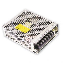
Controller Link Units
| Unit clas- sifica- tion |
Product name |
Specifications | No. of unit numbers allocated |
Current consump- tion (A) |
Model | Stand- ards |
||||
|---|---|---|---|---|---|---|---|---|---|---|
| Communi- cations cable |
Communi- cations type |
Duplex support |
Max. Units mountable per CPU Unit |
5 V DC |
26 V DC |
|||||
| CS1 CPU Bus Unit |
Controller Link Unit  |
Wired shielded twisted-pair cable *1 |
Data links and message service |
No | 8 | 1 | 0.33 | – | CS1W-CLK23 | UC1, N, L, CE |
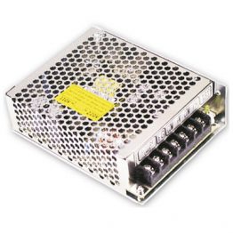
| Controller Link Unit  |
Optical ring H-PCF cable *2 |
Yes. Unit duplexing and cable loop back are supported. |
Non-duplex: 8, Duplex: 11 (6 Units comprising 3 sets of Duplex Units + 5 Non-duplex Units) |
1 | 0.52 | – | CS1W-CLK13 | |||
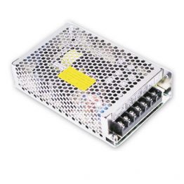
| Controller Link Unit  |
Optical ring GI cable *3 |
1 | 0.65 | – | CS1W-CLK53 | |||||
• ESVC0.5×2C-13262 (Bando Electric Wire: Japanese Company)
• ESNC0.5×2C-99-087B (JMACS Japan Co., Ltd. : Japanese Company)
• ESPC 1P×0.5mm2 (Nagaoka Electric Wire Co.,Ltd.: Japanese Company)
• Li2Y-FCY2×0.56qmm (Kromberg & Schubert, Komtec Department: German Company)
• 1×2×AWG-20PE+Tr.CUSN+PVC (Draka Cables Industrial: Spanish Company)
• #9207 (Belden: US Company)
*2. When using a wire-to-optical (H-PCF) cable, use a H-PCF cable (for both Controller Link and SYSMAC LINK) or a
H-PCF optical fiber cable with connector.
*3. When using a wire-to-optical (GI) cable, use a GI optical cable that matches the specifications.
Accessories
The Optical Fiber Cable Bracket is included in CS1W-CLK13 and CS1W-CLK53.
Controller Link Support Boards
| Product name | Specifications | Accessories | Model | Standards | |
|---|---|---|---|---|---|
| Communications cable |
Communications type |
||||
| Controller Link Support Board for PCI Bus  |
Wired shielded twisted-pair cable |
Data links and message service |
CD-ROM x 1 * INSTALLATION GUIDE (W467) x 1 Communications connector x 1 |
3G8F7-CLK23-E | CE |
| H-PCF optical model | CD-ROM × 1 * INSTALLATION GUIDE (W467) x 1 Optical Fiber Cable Bracket x 1 Power supply connector x 1 |
3G8F7-CLK13-E | |||
| GI optical model | 3G8F7-CLK53-E | ||||
• Controller Link (PCI) Driver
• FinsGataway Version 2003 (PCI-CLK Edition)
• FinsGataway Version 3 (PCI-CLK Edition)
• Setup Diagnostic Utility
• C Library
Repeater Units
| Name | Specifications | Model | Standards |
|---|---|---|---|
| Controller Link Repeater Unit  |
Wire-to-Wire Model | CS1W-RPT01 | UC1, CE |
| Wire-to-Optical (H-PCF) Model *1 | CS1W-RPT02 | ||
| Wire-to-Optical (GI) Model *2 | CS1W-RPT03 |
Note: 1. When using wire-to-optical (H-PCF) cable, use a H-PCF cable (for both Controller Link and SYSMAC LINK) or a
H-PCF optical fiber cable with connector.
2. When using wire-to-optical (GI) cable, use a GI optical cable (for Controller Link).
Relay Terminal Block
| Name | Specifications | Model | Standards |
|---|---|---|---|
| Relay Terminal Blocks for Wired Controller Link Units  |
Used for Wired Controller Link Units (set of 5) | CJ1W-TB101 | – |
Controller Link Units can be replaced without stopping the communications of the entire network if a Relay Terminal Block is installed in advance on the Unit in a Wired Controller Link network. Relay Terminal Blocks cannot be used on Controller Link Support Boards.
Duplex Optical Fiber Cable (H-PCF Cable)
| Name | Application | Specifications | Model | Standards |
|---|---|---|---|---|
| Duplex Optical Fiber Cable |
CS1W-CLK13 or CS1W-CLK12-V1 * in a CS1D system |
H-PCF cable for connecting Duplex Controller Link Units Cable length: 50 cm |
CS1D-CN051 | – |
This cable is used to connect Units in active mode (ACT) and standby mode (STB) in a CS1D Duplex System.
* Discontinuation models in July 2012.
H-PCF Cables and Optical Connectors
| Name | Application/construction | Specifications | Model | Standards | |||
|---|---|---|---|---|---|---|---|
| Optical Fiber Cables | Controller Link, SYSMAC LINK, SYSBUS |
 1. Optical fiber |
Two- core optical cable with tension member |
Black 10 m | S3200-HCCB101 | – | |
| Black 50 m | S3200-HCCB501 | ||||||
| Black 100 m | S3200-HCCB102 | ||||||
| Black 500 m | S3200-HCCB502 | ||||||
| Black 1000 m | S3200-HCCB103 | ||||||
| Orange 10 m | S3200-HCCO101 | ||||||
| Orange 50 m | S3200-HCCO501 | ||||||
| Orange 100 m | S3200-HCCO102 | ||||||
| Orange 500 m | S3200-HCCO502 | ||||||
| Orange 1000 m | S3200-HCCO103 | ||||||
| Optical Connectors (Crimp-cut) |
 |
Controller Link: CS1W-CLK13 CS1W-CLK12-V1 *1 3G8F7-CLK13-E 3G8F7-CLK12-EV1 *1 CS1W-RPT02 SYSMAC LINK: CS1W-SLK11 3G8F7-SLK11-E C200HW-SLK13/14 *1 |
Half lock | S3200-COCF2571 | |||
 |
Controller Link: CS1W-CLK13 CS1W-CLK12-V1 *1 3G8F7-CLK13-E 3G8F7-CLK12-EV1 *1 CS1W-RPT02 SYSMAC LINK: 3G8F7-SLK11-E |
Full lock | S3200-COCF2071 *2 |
||||
*2. Full-lock Optical Connectors (Crimp-cut) (S3200-COCF2071) cannot be used with the CS1W-SLK11. Use a Half-lock
Cable (S3200- COCF2571) or a H-PCF Optical Fiber Cable with Connector (S3200-CN[][][]-[][]-[][]).
H-PCF Optical Fiber Cables with Connectors (Black Composite Cables with Two-Optical Lines and Two Power Supply Lines)
| Application | Appearance | Model | Standards |
|---|---|---|---|
| Controller Link, SYSMAC LINK |
 |
S3200-CN[][][]-20-20 | – |
 |
S3200-CN[][][]-20-25 | ||
 |
S3200-CN[][][]-25-25 |
Optical connectors for H-PCF Optical Cables with Connectors are adhesive polished.
Cable Length
The following cable lengths are available: 2 m, 5 m, 15 m, and 20 m. For lengths of 21 m or more, contact your OMRON sales representative.
Model Numbers

Optical Connector Assembly Tool
| Name | Applicable Unit | Model | Manufacturer | Standards |
|---|---|---|---|---|
| Optical Fiber Assembly Tool * |
This tool is used on site for mounting crimp-cut connectors and hard plastic-clad silica optical fiber for optical transmission systems of SYSMAC C-series SYSBUS, SYSMAC LINK, and Controller Link. |
CAK-0057 | Sumitomo Electric Industries, Ltd. |
– |
cables with preattached connectors or having a qualified technician assemble the cables.
Communications Specifications
| Items | Specifications | ||
|---|---|---|---|
| Model | CS1W-CLK23 3G8F7-CLK23-E CS1W-CLK21-V1 *1 3G8F7-CLK21-EV1 *1 |
CS1W-CLK13 3G8F7-CLK13-E CS1W-CLK12-V1 *1 3G8F7-CLK12-EV1 *1 |
CS1W-CLK53 3G8F7-CLK53-E CS1W-CLK52-V1 *1 3G8F7-CLK52-EV1 *1 |
| Type | Wired (shielded twisted-pair cable) | Optical Ring (H-PCF cable) | Optical Ring (GI cable) |
| Communications method | N:N token-bus method | N:N token-ring method (token-ring mode) N:N token-bus method (token-bus mode) |
|
| Code | Manchester code | ||
| Modulation | Baseband code | ||
| Synchronization | Flag synchronization (conforms to HDLC frames) | ||
| Transmission path format | Multidrop method (bus type) | Ring method (token-ring mode) Daisy-chain method (token-ring mode) |
|
| Transmission speed | The following are the maximum transmission distances depending on the transmission speed. 2 Mbits/s: 500 m 1 Mbits/s: 800 m 500 kbits/s: 1 km |
2 Mbits/s | |
| Maximum transmission distance |
20 km | 30 km | |
| Maximum distance between nodes |
Not specified. (Maximum transmission distance must be satisfied for the entire system.) |
Crimp-cut: 800 m Adhesive polishing: 1 km *2 |
62.5/125 μm: 2 km 50/125 μm: 1 km |
| Medium | Specified shielded twist-pair cable Two signal wires, one shield |
H-PCF cable (two-core optical cable) |
GI cable (two-core optical cable: 62.5/125 μm, 50/ 125 μm) |
| Node connection method | PLC: Connection to terminal block Computer: Connection using special (supplied) connector |
Connection using special connector (full-lock connector or half-lock connector) |
Connection using ST connector |
| Maximum number of nodes | 32 or 62 nodes *3 *4 | 62 *5 | |
| Applicable Programming Devices |
CX-Integrator in CX-One, CX-Net in CX-Programmer *4, and Programming Console | ||
| Communications functions | Data links and message service | ||
| Number of data link words | Send words per node: 4,000 words max. (CS1W-CLK[]3), 1,000 words max. (All other Units) Number of send/receive words per node: 12,000 words max. (Pre-Ver. 1.2) 20,000 words max. (unit Ver. 1.2 or later) Total number of send words per network: 62,000 words max. |
||
| Data link areas | PLC: Bit areas (CIO Area, Work Area, Link Area *6), Data Memory (DM), Extended DM Area (EM) Computer: FinsGateway event memory |
||
| Message length | 2,012 bytes max. (including the header) | ||
| RAS functions | Polling node backup function Self-diagnosis function (hardware checking at startup) Echoback test and broadcast test (using the FINS command) Watchdog timer Error log function |
Polling node backup function Self-diagnosis function (hardware checking at startup) Echoback test and broadcast test (using the FINS command) Watchdog timer Error log function Node bypass function Transmission path duplication (for ring method in token-ring mode only) Disconnect detection and notification (token-ring mode only) Node connection configuration data reading (for ring method in token-ring mode only) Duplex operation of Communications Units *7 |
|
| Error control | Manchester code check CRC check (CCITT X16+X12+X5+1) |
||
*2. The maximum distance between nodes depends on the processing method for connectors and cables.
*3. With wired models, the maximum number of nodes is 32 if Repeater Units are not used. A Repeater Unit is required
when building a network with more than 32 nodes. If a Repeater Unit is used, be sure to use only the following
Controller Link Units or Boards and set the Wired Network 62 Node Enable Bit in the DM Parameter Area software
switches at all nodes.
CS1W-CLK23/CLK21-V1 *1
CJ1W-CLK23/CLK21-V1 *1
3G8F7-CLK23-E/CLK21-EV1 *1
*4. CX-Net in CX-Programmer version 3.1 or earlier can be used only in a system with a maximum of 32 nodes (node
address 1 to 32). If a system is to be used with a maximum of 62 nodes (node addresses 1 to 62), use CX-Net in
CX-Programmer version 3.2 or higher or the CX-Integrator.
*5. If duplex Controller Link Units are used, the effective maximum number of nodes will be 62 (i.e., the maximum
number of nodes in standby mode (STB)).
*6. CS-series PLCs do not have a Link Area, but LR000 to LR199 are automatically converted CIO 1000 to CIO 1199.
*7. Only when a CS1W-CLK13/12-V1 *1/53/52-V1 *1 installed in a CS1D system is used in token ring mode.
Individual Specifications
Controller Link Units
| Item | Specifications | |||
|---|---|---|---|---|
| Model | CS1W-CLK23 CS1W-CLK21-V1 * |
CS1W-CLK13 CS1W-CLK12-V1 * |
CS1W-CLK53 CS1W-CLK52-V1 * |
|
| Supported PLC | All CS-series CPU Units | |||
| Number of mountable Units | Unit version 1.2 or later: 8 Units max., Pre-Ver. 1.2: 4 Units max. | |||
| Installation site | Install onto a CPU Backplane or CS-series Expansion Backplane (classified as a CPU Bus Unit). | |||
| Storage location for network parameters and manually set data tables |
CPU Bus Unit Area (in the CPU Unit parameter area) | |||
| Storage location for routing tables | CPU Unit parameter area | |||
| Weight | 220 g | 300 g (excluding mounting bracket) |
300 g (excluding mounting bracket) |
|
| Current consumption |
5 V in PLC | 0.33 A | 0.52 A | 0.65 A |
| 26 V in PLC | – | – | – | |
| External 24 V | – | 0.20 A | 0.26 A | |
* Discontinuation models in July 2012.
Controller Link Support Boards (for PCI Bus)
| Item | Specifications | |||
|---|---|---|---|---|
| Models | 3G8F7-CLK23-E | 3G8F7-CLK13-E | 3G8F7-CLK53-E | |
| Applicable computers | IBM PC/AT or compatible CPU: Intel Celeron 400 MHz or better Main memory: 128 MB minimum One or more PCI bus slots (PCI bus revision 2.0 or higher, power supply: 5 V) Available hard disk space: 70 MB min. CD-ROM drive: One required for installation Display: VGA (640 × 480 (pixels) min.) (Other conditions conform to the OS.) |
|||
| Compatible OS | FinsGateway Version 2003 *1 Windows 10 (32bit) Windows 8 (32bit) Windows 7 (32bit) Professional Windows 7 (32bit) Home Premium Windows Vista Business Windows Vista Home Premium FinsGateway Version 3 *2 Windows XP Professional Windows XP Home Edition Windows 2000 Professional Windows NT 4.0 (Service Pack 3 or higher) Windows ME Windows 98SE |
|||
| Weight | 104 g | 120 g (excluding mounting bracket) |
124 g (excluding mounting bracket) |
|
| Current consumption |
5 V in PLC | 0.35 A | 0.54 A | 0.60 A |
| External 24 V | – | 0.35 A | 0.35 A | |
*2. Install FinsGateway version 3 if the operating system is Windows NT 4.0 (Service pack 3 or higher), Windows ME, or
Windows 98SE. In that case, however, the new functions of Controller Link Support Boards for the PCI Bus cannot
be used (i.e., automatic data link creation with 1:N allocation, changing data link tables with active data links, 62-
node setting for wired models, and maximum of 4000 send words).
Repeater Units
| Item | Specifications | ||
|---|---|---|---|
| Model | CS1W-RPT01 | CS1W-RPT02 | CS1W-RPT03 |
| Supported Units and Boards | All wired Controller Link Units and Boards Note: If a maximum of 62 nodes is used, models that support 62 nodes must be used. |
||
| Transmission path | Wire-to-wire | Wire-to-optical (H-PCF) | Wire-to-optical (GI) |
| Transmission path format | Multi-drop Tree |
1:1 | 1:1 |
| Installation | Repeater Units are not mounted to the PLC. They are mounted separately with screws or on a DIN Track. |
||
| Weight | 130 g | 130 g (excluding mounting bracket) |
130 g (excluding mounting bracket) |
| Allowable power supply voltage range |
20.4 to 26.4 VDC (24 VDC – 15 V to +10%) | ||
| Current consumption | 0.06 A at 24 VDC | 0.06 A at 24 VDC | 0.07 A at 24 VDC |
| Inrush current | 2.5 A max. (24 VDC with rise time of 5 ms) | ||
Repeater Units are used to expand the Controller Link network for wired models. For Wired-to-optical Repeater Units, always use a set of two (1:1). Optical Ring Controller Link Units and Boards cannot be connected to the optical cable section between Repeater Units.
(Unit: mm)
CS1W-CLK23/CS1W-CLK21-V1 *

CS1W-CLK13/CS1W-CLK12-V1 *

CS1W-CLK53/CS1W-CLK52-V1 *

Note: The dimensions in parentheses are for the CS1W-CLK53 (including the terminal cover).
* Discontinuation models in July 2012.
|
Catalog Name
|
Catalog Number
[size] |
Last Update
|
|---|---|---|
| – [1352KB] |
Dec 17, 2018 |


Reviews
There are no reviews yet.