
Description
• Select the best interface for each application: Fujitsu connectors and MIL connectors.
• Select sinking outputs or sourcing outputs. The CJ1W-MD232 has load short-circuit protection.
• The ON and OFF response times can be set to between 0 and 32 ms in the Setup in the CPU Unit.
• Mixed I/O Units with 5-V TTL inputs are also available. *
• A wide variety of Connector-Terminal Block Conversion Units are available to allow you to easily wire external I/O devices.
* Applies to the CJ1W-MD563.
International Standards
- The standards are abbreviated as follows: U: UL, U1: UL (Class I Division 2 Products for Hazardous Locations), C: CSA, UC: cULus, UC1: cULus (Class I Division 2 Products for Hazardous Locations), CU: cUL, N: NK, L: Lloyd, and CE: EC Directives.
- Contact your OMRON representative for further details and applicable conditions for these standards.
Mixed I/O Units
| Unit type |
Product name |
Specifications | Current con- sump- tion (A) |
Model | Stand- ards |
||||||
|---|---|---|---|---|---|---|---|---|---|---|---|
| Output type |
I/O points |
Input voltage, Input current |
Commons | Ex- ternal con- nec- tion |
No. of words allo- cated |
5 V |
24 V |
||||
| Maximum switching capacity |
|||||||||||
| CJ1 Basic I/O Units |
DC Input/ Tran- sistor Output Units  |
Sinking | 16 inputs |
24 VDC, 7 mA |
16 points, 1 common |
Fujitsu con- nector |
2 words |
0.13 | — | CJ1W-MD231 | UC1, N, CE |
| 16 outputs |
250 VAC/ 24 VDC, 0.5 A |
16 points, 1 common |
|||||||||
| Sinking | 16 inputs |
24 VDC, 7 mA |
16 points, 1 common |
MIL con- nector |
2 words |
0.13 | — | CJ1W-MD233 | UC1, N, CE |
||
| 16 outputs |
12 to 24 VDC, 0.5 A |
16 points, 1 common |
|||||||||
| Sinking | 32 inputs |
24 VDC, 4.1 mA |
16 points, 1 common |
Fujitsu con- nector |
4 words |
0.14 | — | CJ1W-MD261 | |||
| 32 outputs |
12 to 24 VDC, 0.3 A |
16 points, 1 common |
|||||||||
| Sinking | 32 inputs |
24 VDC, 4.1 mA |
16 points, 1 common |
MIL con- nector |
4 words |
0.14 | — | CJ1W-MD263 | |||
| 32 outputs |
12 to 24 VDC, 0.3 A |
16 points, 1 common |
|||||||||
| Sourcing | 16 inputs |
24 VDC, 7 mA |
16 points, 1 common |
MIL con- nector |
2 words |
0.13 | — | CJ1W-MD232 | UC1, N, L, CE |
||
| 16 outputs |
24 VDC, 0.5 A Short- circuit protection |
16 points, 1 common |
|||||||||
| TTL I/O Units  |
— | 32 inputs |
5 VDC, 35 mA |
16 points, 1 common |
MIL con- nector |
4 words |
0.19 | — | CJ1W-MD563 | UC1, N, CE |
|
| 32 outputs |
5 VDC, 35 mA |
16 points, 1 common |
|||||||||
Accessories
Connectors are not included for models with connectors. Either use one of the applicable connector listed below or use an applicable Connector-Terminal Block Conversion Unit or I/O Relay Terminal. For details on wiring methods, refer to External Interface.
Applicable Connectors
Fujitsu Connectors for 32-input, 32-output, 64-input, 64-output, 32-input/32-output, and 16-input/16-output Units
| Name | Con- nection |
Remarks | Applicable Units | Model | Stand- ards |
|
|---|---|---|---|---|---|---|
| 40-pin Con- nectors |
Soldered | FCN-361J040-AU | Connector | Fujitsu Connectors: CJ1W-ID231(32 inputs): 1 per Unit CJ1W-ID261 (64 inputs): 2 per Unit CJ1W-OD231 (32 outputs): 1 per Unit CJ1W-OD261 (64 outputs): 2 per Unit CJ1W-MD261 (32 inputs, 32 outputs): 2 per Unit |
C500-CE404 | — |
| FCN-360C040-J2 | Connector Cover |
|||||
| Crimped | FCN-363J040 | Housing | C500-CE405 | |||
| FCN-363J-AU | Contactor | |||||
| FCN-360C040-J2 | Connector Cover |
|||||
| Pressure welded |
FCN-367J040-AU/F | C500-CE403 | ||||
| 24-pin Con- nectors |
Soldered | FCN-361J024-AU | Connector | Fujitsu Connectors: CJ1W-MD231 (16 inputs, 16 outputs): 2 per Unit |
C500-CE241 | |
| FCN-360C024-J2 | Connector Cover |
|||||
| Crimped | FCN-363J024 | Socket | C500-CE242 | |||
| FCN-363J-AU | Contactor | |||||
| FCN-360C024-J2 | Connector Cover |
|||||
| Pressure welded |
FCN-367J024-AU/F | C500-CE243 | ||||
MIL Connectors for 32-input, 32-output, 64-input, 64-output, 32-input/32-output, and 16-input/16-output Units
| Name | Con- nection |
Remarks | Applicable Units | Model | Stand- ards |
|---|---|---|---|---|---|
| 40-pin Con- nectors |
Pressure welded |
FRC5-AO40-3TOS | MIL Connectors: CJ1W-ID232/233 (32 inputs): 1 per Unit CJ1W-OD232/233/234 (32 outputs):1 per Unit CJ1W-ID262 (64 inputs): 2 per Unit CJ1W-OD262/263 (64 outputs): 2 per Unit CJ1W-MD263/563 (32 inputs, 32 outputs): 2 per Unit |
XG4M-4030-T | — |
| Crimped | – | XG5N-401 * | |||
| 20-pin Con- nectors |
Pressure welded |
FRC5-AO20-3TOS | MIL Connectors: CJ1W-MD232/233 (16 inputs, 16 outputs): 2 per Unit |
XG4M-2030-T | — |
| Crimped | – | XG5N-201 * |
* Crimp Contacts are also required. Refer to Data Sheet for details.
Applicable Connector-Terminal Block Conversion Units
Size and Mounting are Refer to Data Sheet.
| Type/ Series |
Num- ber of poles |
Wiring method |
Ter- minal type |
Com- mon termi- nals |
Bleeder resis- tance |
Indi- cators |
I/O Units | Model * | Stand- ards |
|---|---|---|---|---|---|---|---|---|---|
| General- purpose devices, PLC/ XW2R |
20 | Phillips screw  |
M3 | No | No | No | CJ1W-MD231 CJ1W-MD232 CJ1W-MD233 |
XW2R-J20GD-T | ― |
| 34 | CJ1W-MD261 | XW2R-J34GD-C1 | |||||||
| XW2R-J34GD-C3 | |||||||||
| CJ1W-MD263 | XW2R-J34GD-C2 | ||||||||
| XW2R-J34GD-C4 | |||||||||
| CJ1W-MD563 | XW2R-J34GD-C2 | ||||||||
| XW2R-J34GD-C4 | |||||||||
| 20 | Slotted screw (rise up)  |
M3 (Euro- pean type) |
CJ1W-MD231 CJ1W-MD232 CJ1W-MD233 |
XW2R-E20GD-T | |||||
| 34 | CJ1W-MD261 | XW2R-E34GD-C1 | |||||||
| XW2R-E34GD-C3 | |||||||||
| CJ1W-MD263 | XW2R-E34GD-C2 | ||||||||
| XW2R-E34GD-C4 | |||||||||
| CJ1W-MD563 | XW2R-E34GD-C2 | ||||||||
| XW2R-E34GD-C4 | |||||||||
| 20 | Push-in spring  |
Clamp | CJ1W-MD231 CJ1W-MD232 CJ1W-MD233 |
XW2R-P20GD-T | |||||
| 34 | CJ1W-MD261 | XW2R-P34GD-C1 | |||||||
| XW2R-P34GD-C3 | |||||||||
| CJ1W-MD263 | XW2R-P34GD-C2 | ||||||||
| XW2R-P34GD-C4 | |||||||||
| CJ1W-MD563 | XW2R-P34GD-C2 | ||||||||
| XW2R-P34GD-C4 |
Note: For the combination of Input Units with Connector-Terminal Block Conversion Units, refer to 2. Connecting
Connector-Terminal Block Conversion Units.
* Representative models only. For details, refer to the XW2R series catalog (Cat. No. G077).
Connecting Cables for Connector-Terminal Block Conversion Units
| Appearance | Connectors | Cable lenght [m] | Model |
|---|---|---|---|
XW2Z-[][][]A |
One 24-pin Fujitsu Connector to One 20-pin MIL Connector |
0.5 | XW2Z-050A |
| 1 | XW2Z-100A | ||
| 1.5 | XW2Z-150A | ||
| 2 | XW2Z-200A | ||
| 3 | XW2Z-300A | ||
| 5 | XW2Z-500A | ||
| 7 | XW2Z-700A | ||
| 10 | XW2Z-010A | ||
| 15 | XW2Z-15MA | ||
| 20 | XW2Z-20MA | ||
XW2Z-[][][]X |
One 20-pin MIL Connector to One 20-pin MIL Connector |
0.5 | XW2Z-C50X |
| 1 | XW2Z-100X | ||
| 2 | XW2Z-200X | ||
| 3 | XW2Z-300X | ||
| 5 | XW2Z-500X | ||
| 10 | XW2Z-010X | ||
XW2Z-[][][]PF |
One 40-pin Fujitsu Connector to One 40-pin MIL Connector |
0.5 | XW2Z-050PF |
| 1 | XW2Z-100PF | ||
| 1.5 | XW2Z-150PF | ||
| 2 | XW2Z-200PF | ||
| 3 | XW2Z-300PF | ||
| 5 | XW2Z-500PF | ||
XW2Z-[][][]PM |
One 40-pin MIL Connector to One 40-pin MIL Connector |
0.5 | XW2Z-050PM |
| 1 | XW2Z-100PM | ||
| 1.5 | XW2Z-150PM | ||
| 2 | XW2Z-200PM | ||
| 3 | XW2Z-300PM | ||
| 5 | XW2Z-500PM |
Applicable I/O Relay Terminals
Size (horizontal mounting) and Mounting are Refer to Data Sheet.
| Type/ Series |
Specifications | Model | Stand- ards |
|||||
|---|---|---|---|---|---|---|---|---|
| Classifi- cation |
Po- lar- ity |
Number of points |
Rated ON cur- rent at con- tacts |
Rated vol- tage |
||||
| Push-In Plus terminal block/ G70V |
In- puts |
DC inputs |
NPN | 16 (SPST- NO × 16) |
50 mA | 24 VDC | G70V-SID16P *4 | UC, CE (TÜV certi- fied) |
| PNP | G70V-SID16P-1 *4 | |||||||
| NPN | G70V-SID16P-C16 *5 | |||||||
| PNP | G70V-SID16P-1-C16 *5 | |||||||
| Out- puts |
Relay outputs |
NPN | 16 (SPDT × 16) |
6 A/ point, 10 A/ common |
G70V-SOC16P *4 | |||
| PNP | G70V-SOC16P-1 *4 | |||||||
| NPN | G70V-SOC16P-C4 *6 | |||||||
| PNP | G70V-SOC16P-1-C4 *6 | |||||||
| Standard/ G7TC |
In- puts |
AC inputs |
NPN | 16 (SPST- NO × 16) |
1A | 100/(110) VAC |
G7TC-IA16 AC100/110 | U, C |
| 200/(220) VAC |
G7TC-IA16 AC200/220 | |||||||
| DC inputs |
12 VDC | G7TC-ID16 DC12 | ||||||
| 24 VDC | G7TC-ID16 DC24 | |||||||
| 100/110 VDC |
G7TC-ID16 DC100/110 | |||||||
| Out- puts |
Relay outputs |
NPN | 8 (SPST- NO × 8) |
5A | 12 VDC | G7TC-OC08 DC12 | ||
| 24 VDC | G7TC-OC08 DC24 | |||||||
| 16 (SPST- NO × 16) |
12 VDC | G7TC-OC16 DC12 | ||||||
| 24 VDC | G7TC-OC16 DC24 | |||||||
| PNP | 16 (SPST- NO × 16) |
12 VDC | G7TC-OC16-1 DC12 | |||||
| 24 VDC | G7TC-OC16-1 DC24 | |||||||
| High- capacity socket/ G70A *1 (Socket only) |
In- puts |
Relay inputs |
NPN/ PNP |
16 (SPDT × 16 possible with G2R Relays) |
100 mA | 110 VDC max., 240 VAC max. *2 |
G70A-ZOC16-5 | U, C, CE (VDE certi- fied) |
| Out- puts |
Relay outputs |
NPN | 10 A (Terminal block allowable |
24 VDC | G70A-ZOC16-3 | |||
| PNP | G70A-ZOC16-4 | |||||||
| Space- saving/ Vertical type G70D-V |
Out- puts |
Relay outputs |
NPN | 16 (SPST- NO × 16) |
5 A or 3 A *3 |
24 VDC | G70D-VSOC16 | U, C, CE (VDE certi- fied) |
| MOSFET relay outputs |
0.3 A | G70D-VFOM16 | ||||||
| Space- saving/ Flat type G70D |
Relay outputs |
NPN | 8 (SPST- NO × 8) |
5 A | G70D-SOC08 | – | ||
| 16 (SPST- NO × 16) |
3 A | G70D-SOC16 | ||||||
| PNP | 16 (SPST- NO × 16) |
3 A | G70D-SOC16-1 | |||||
| MOSFET relay outputs |
NPN | 16 (SPST- NO × 16) |
0.3 A | G70D-FOM16 | ||||
| PNP | G70D-FOM16-1 | |||||||
| High- ca- pacity, space- saving/ G70R |
Out- puts |
Relay outputs |
NPN | 8 (SPST- NO × 8) |
10 A | 24 VDC | G70R-SOC08 | – |
*1. G70A is a I/O terminal socket product. Relay is not provided with the socket. Be sure to order a relay, timer separately.
*2. Each relay to be mounted must incorporate a coil that has proper specifications within the maximum rated voltage range.
*3. Eight or fewer points ON: 5 A, Nine or more points ON: 3 A.
*4. Internal common at terminal block: No internal connections
*5. Internal common at terminal block: Internal IO common 16 points internally connected
*6. Internal common at terminal block: Every 4 points internally connected at terminal block middle row.
Note: 1. For the combination of Input Units with I/O Relay Terminal and Connecting Cables, refer to 3. Connecting I/O
Relay Terminals.
2. Please refer to each Datasheet about details.
3. When the G7TC is used with an AC rated voltage, three rated currents can be used.
If a coil voltage of 110 or 220 VAC is used, 50 Hz cannot be used.
Cables for I/O Relay Terminals
| Type | Name | I/O Classifi- cation |
Appearance | Cable length L (mm) |
Models |
|---|---|---|---|---|---|
| Fujitsu connectors (24 pins) |
Cables with Connectors (1:1) XW2Z-R[]C |
16 I/O points |
 |
1,000 | XW2Z-R100C |
| 1,500 | XW2Z-R150C | ||||
| 2,000 | XW2Z-R200C | ||||
| 3,000 | XW2Z-R300C | ||||
| 5,000 | XW2Z-R500C | ||||
| Fujitsu connectors (40 pins) |
Cables with Connectors (1:2) XW2Z-RI[]C-[] XW2Z-RO[]C-[] |
32 input points |
 |
(A) 1,000 (B) 750 |
XW2Z-RI100C-75 |
| (A) 1,500 (B) 1,250 |
XW2Z-RI150C-125 | ||||
| (A) 2,000 (B) 1,750 |
XW2Z-RI200C-175 | ||||
| (A) 3,000 (B) 2,750 |
XW2Z-RI300C-275 | ||||
| (A) 5,000 (B) 4,750 |
XW2Z-RI500C-475 | ||||
| 32 output points |
(A) 1,000 (B) 750 |
XW2Z-RO100C-75 | |||
| (A) 1,500 (B) 1,250 |
XW2Z-RO150C-125 | ||||
| (A) 2,000 (B) 1,750 |
XW2Z-RO200C-175 | ||||
| (A) 3,000 (B) 2,750 |
XW2Z-RO300C-275 | ||||
| (A) 5,000 (B) 4,750 |
XW2Z-RO500C-475 | ||||
| MIL connectors (20 pins) |
Cables with Connectors (1:1) XW2Z-RI[]C XW2Z-RO[]C |
16 I/O points |
 |
250 | XW2Z-RI25C |
| 500 | XW2Z-RI50C | ||||
| 250 | XW2Z-RO25C | ||||
| 500 | XW2Z-RO50C | ||||
| MIL connectors (40 pins) |
Cables with Connectors (1:2) XW2Z-RO[]-[]-D1, XW2Z-RI[]-[]-D1 |
32 I/O points |
 |
(A) 500 (B) 250 |
XW2Z-RO50-25-D1 |
| (A) 750 (B) 500 |
XW2Z-RO75-50-D1 | ||||
| (A) 1,000 (B) 750 |
XW2Z-RO100-75-D1 | ||||
| (A) 1,500 (B) 1,250 |
XW2Z-RO150-125-D1 | ||||
| (A) 2,000 (B) 1,750 |
XW2Z-RO200-175-D1 | ||||
| (A) 3,000 (B) 2,750 |
XW2Z-RO300-275-D1 | ||||
| (A) 5,000 (B) 4,750 |
XW2Z-RO500-475-D1 | ||||
| (A) 500 (B) 250 |
XW2Z-RI50-25-D1 | ||||
| (A) 750 (B) 500 |
XW2Z-RI75-50-D1 | ||||
| (A) 1,000 (B) 750 |
XW2Z-RI100-75-D1 | ||||
| (A) 1,500 (B) 1,250 |
XW2Z-RI150-125-D1 | ||||
| (A) 2,000 (B) 1,750 |
XW2Z-RI200-175-D1 | ||||
| (A) 3,000 (B) 2,750 |
XW2Z-RI300-275-D1 | ||||
| (A) 5,000 (B) 4,750 |
XW2Z-RI500-475-D1 |
Note: Refer to the Datasheet for the XW2Z-R Cables for I/O Relay Terminals (Cat. No. G126).
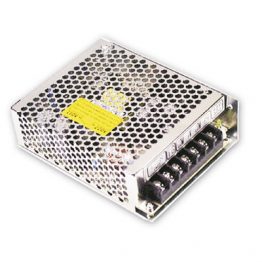
CJ1W-MD231 DC Input/Transistor Output Unit (24 VDC, 16 Inputs/16 Outputs)
| Name | 16-point DC Input/16-point Transistor Output Unit with Fujitsu Connectors (Sinking Outputs) | ||
|---|---|---|---|
| Model | CJ1W-MD231 | ||
| Output section (CN1) | Input section (CN2) | ||
| Rated Voltage | 12 to 24 VDC | Rated Input Voltage | 24 VDC |
| Operating Load Voltage Range |
10.2 to 26.4 VDC | Operating Input Voltage |
20.4 to 26.4 VDC |
| Maximum Load Current |
0.5 A/point, 2.0 A/Unit | Input Impedance | 3.3 kΩ |
| Maximum Inrush Current |
4.0 A/point, 10 ms max. | Input Current | 7 mA typical (at 24 VDC) |
| Leakage Current | 0.1 mA max. | ON Voltage/ON Current |
14.4 VDC min./3 mA min. |
| Residual Voltage | 1.5 V max. | OFF Voltage/OFF Current |
5 VDC max./1 mA max. |
| ON Response Time |
0.1 ms max. | ON Response Time | 8.0 ms max. (Can be set to between 0 and 32 in the Setup.) * |
| OFF Response Time |
0.8 ms max. | ||
| No. of Circuits | 16 (16 points/common, 1 circuit) | OFF Response Time | 8.0 ms max. (Can be set to between 0 and 32 in the Setup.) * |
| Fuse | None | ||
| External Power Supply |
10.2 to 26.4 VDC, 20 mA min. | No. of Circuits | 16 (16 points/common, 1 circuit) |
| Number of Simultaneously ON Points |
75% (at 24 VDC) | ||
| Insulation Resistance |
20 MΩ min. between the external terminals and the GR terminal (at 100 VDC) | ||
| Dielectric Strength |
1,000 VAC between the external terminals and the GR terminal for 1 minute at a leakage current of 10 mA max. |
||
| Internal Current Consumption |
5 VDC 130 mA max. | ||
| Weight | 90 g max. | ||
| Accessories | None | ||
| Circuit Configuration |
CN1 (OUT) | CN2 (IN) | |
 The signal names of the terminals are the |
  The signal names of the terminals are the |
||
| External connection and terminal-device variable diagram |
CN1 (OUT) | CN2 (IN) | |
 When wiring, pay careful attention to the polarity |
 When wiring, pay careful attention to the polarity |
||
times are set to 0 ms due to internal element delays.
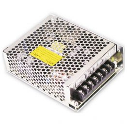
CJ1W-MD233 DC Input/Transistor Output Unit (24 VDC, 16 Inputs/16 Outputs)
| Name | 16-point DC Input/16-point Transistor Output Unit with MIL Connectors (Sinking Outputs) | ||
|---|---|---|---|
| Model | CJ1W-MD233 | ||
| Output section (CN1) | Input section (CN2) | ||
| Rated Voltage | 12 to 24 VDC | Rated Input Voltage | 24 VDC |
| Operating Load Voltage Range |
10.2 to 26.4 VDC | Operating Input Voltage |
20.4 to 26.4 VDC |
| Maximum Load Current |
0.5 A/point, 2.0 A/Unit | Input Impedance | 3.3 kΩ |
| Maximum Inrush Current |
4.0 A/point, 10 ms max. | Input Current | 7 mA typical (at 24 VDC) |
| Leakage Current | 0.1 mA max. | ON Voltage/ON Current |
14.4 VDC min./3 mA min. |
| Residual Voltage | 1.5 V max. | OFF Voltage/OFF Current |
5 VDC max./1 mA max. |
| ON Response Time |
0.1 ms max. | ON Response Time | 8.0 ms max. (Can be set to between 0 and 32 in the Setup.) * |
| OFF Response Time |
0.8 ms max. | ||
| No. of Circuits | 16 (16 points/common, 1 circuit) | OFF Response Time | 8.0 ms max. (Can be set to between 0 and 32 in the Setup.) * |
| Fuse | None | ||
| External Power Supply |
10.2 to 26.4 VDC, 20 mA min. | No. of Circuits | 16 (16 points/common, 1 circuit) |
| Number of Simultaneously ON Points |
75% (at 24 VDC) | ||
| Insulation Resistance |
20 MΩ min. between the external terminals and the GR terminal (at 100 VDC) | ||
| Dielectric Strength |
1,000 VAC between the external terminals and the GR terminal for 1 minute at a leakage current of 10 mA max. |
||
| Internal Current Consumption |
5 VDC 130 mA max. | ||
| Weight | 90 g max. | ||
| Accessories | None | ||
| Circuit Configuration |
CN1 (OUT) | CN2 (IN) | |
 The signal names of the terminals are the |
  The signal names of the terminals are the |
||
| External connection and terminal-device variable diagram |
CN1 (OUT) | CN2 (IN) | |
 When wiring, pay careful attention to the polarity |
 When wiring, pay careful attention to the polarity |
||
times are set to 0 ms due to internal element delays.
CJ1W-MD261 DC Input/Transistor Output Unit (24 VDC 32 Inputs/32 Outputs)
| Name | 32-point DC Input/32-point Transistor Output Unit with Fujitsu Connectors (Sinking Outputs) | ||
|---|---|---|---|
| Model | CJ1W-MD261 | ||
| Output section (CN1) | Input section (CN2) | ||
| Rated Voltage | 12 to 24 VDC | Rated Input Voltage | 24 VDC |
| Operating Load Voltage Range |
10.2 to 26.4 VDC | Operating Input Voltage |
20.4 to 26.4 VDC |
| Maximum Load Current |
0.3 A/point, 1.6 A/common, 3.2 A/Unit | Input Impedance | 5.6 kΩ |
| Maximum Inrush Current |
3.0 A/point, 10 ms max. | Input Current | 4.1 mA typical (at 24 VDC) |
| Leakage Current | 0.1 mA max. | ON Voltage/ON Current |
19.0 VDC min./3 mA min. *2 |
| Residual Voltage | 1.5 V max. | OFF Voltage/OFF Current |
5 VDC max./1 mA max. |
| ON Response Time |
0.5 ms max. | ON Response Time | 8.0 ms max. (Can be set to between 0 and 32 in the Setup.) *1 |
| OFF Response Time |
1.0 ms max. | ||
| No. of Circuits | 32 (16 points/common, 2 circuits) | OFF Response Time | 8.0 ms max. (Can be set to between 0 and 32 in the Setup.) *1 |
| Fuse | None | ||
| External Power Supply |
10.2 to 26.4 VDC, 30 mA min. | No. of Circuits | 32 (16 points/common, 2 circuits) |
| Number of Simultaneously ON Points |
75% (24 points) (at 24 VDC) |
||
| Insulation Resistance |
20 MΩ min. between the external terminals and the GR terminal (at 100 VDC) | ||
| Dielectric Strength |
1,000 VAC between the external terminals and the GR terminal for 1 minute at a leakage current of 10 mA max. |
||
| Internal Current Consumption |
5 VDC 140 mA max. | ||
| Weight | 110 g max. | ||
| Accessories | None | ||
| Circuit Configuration |
CN1 (OUT) | CN2 (IN) | |
 The signal names of the terminals are the |
 The signal names of the terminals are the |
||
 |
|||
| External connection and terminal-device variable diagram |
CN1 (OUT) | CN2 (IN) | |
 Be sure to wire both terminals A19 and A9 |
 Be sure to wire both pins A9 and A18 (COM2) of |
||
response times are set to 0 ms due to internal element delays.
*2. Observe the following restrictions when connecting to a 2-wire sensor.
• Make sure the input power supply voltage is larger than the ON voltage (19 V) plus the residual voltage of the
sensor (approx. 3 V).
• Use a sensor with a minimum load current of 3 mA min.
• Connect bleeder resistance if you connect a sensor with a minimum load current of 5 mA or higher.
CJ1W-MD263 DC Input/Transistor Output Unit (24 VDC 32 Inputs/32 Outputs)
| Name | 32-point DC Input/32-point Transistor Output Unit with MIL Connectors (Sinking Outputs) | ||
|---|---|---|---|
| Model | CJ1W-MD263 | ||
| Output section (CN1) | Input section (CN2) | ||
| Rated Voltage | 12 to 24 VDC | Rated Input Voltage | 24 VDC |
| Operating Load Voltage Range |
10.2 to 26.4 VDC | Operating Input Voltage |
20.4 to 26.4 VDC |
| Maximum Load Current |
0.3 A/point, 1.6 A/common, 3.2 A/Unit | Input Impedance | 5.6 kΩ |
| Maximum Inrush Current |
3.0 A/point, 10 ms max. | Input Current | 4.1 mA typical (at 24 VDC) |
| Leakage Current | 0.1 mA max. | ON Voltage/ON Current |
19.0 VDC min./3 mA min. *2 |
| Residual Voltage | 1.5 V max. | OFF Voltage/OFF Current |
5 VDC max./1 mA max. |
| ON Response Time |
0.5 ms max. | ON Response Time | 8.0 ms max. (Can be set to between 0 and 32 in the Setup.) *1 |
| OFF Response Time |
1.0 ms max. | ||
| No. of Circuits | 32 (16 points/common, 2 circuits) | OFF Response Time | 8.0 ms max. (Can be set to between 0 and 32 in the Setup.) *1 |
| Fuse | None | ||
| External Power Supply |
10.2 to 26.4 VDC, 30 mA min. | No. of Circuits | 32 (16 points/common, 2 circuits) |
| Number of Simultaneously ON Points |
75% (24 points) (at 24 VDC) |
||
| Insulation Resistance |
20 MΩ min. between the external terminals and the GR terminal (at 100 VDC) | ||
| Dielectric Strength |
1,000 VAC between the external terminals and the GR terminal for 1 minute at a leakage current of 10 mA max. |
||
| Internal Current Consumption |
5 VDC 140 mA max. | ||
| Weight | 110 g max. | ||
| Accessories | None | ||
| Circuit Configuration |
CN1 (OUT) | CN2 (IN) | |
 The signal names of the terminals are the |
 The signal names of the terminals are the |
||
 |
|||
| External connection and terminal-device variable diagram |
CN1 (OUT) | CN2 (IN) | |
 Be sure to wire both terminals 23 and 24 |
 Be sure to wire both pins 23 and 24 (COM2) of |
||
response times are set to 0 ms due to internal element delays.
*2. Observe the following restrictions when connecting to a 2-wire sensor.
• Make sure the input power supply voltage is larger than the ON voltage (19 V) plus the residual voltage of the
sensor (approx. 3 V).
• Use a sensor with a minimum load current of 3 mA min.
• Connect bleeder resistance if you connect a sensor with a minimum load current of 5 mA or higher.
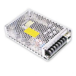
CJ1W-MD232 DC Input/Transistor Output Unit (24 VDC, 16 inputs/16 Outputs)
| Name | 16-point DC Input/16-point Transistor Output Unit with MIL Connectors (Sourcing Outputs) | ||
|---|---|---|---|
| Model | CJ1W-MD232 | ||
| Output section (CN1) | Input section (CN2) | ||
| Rated Voltage | 24 VDC | Rated Input Voltage | 24 VDC |
| Operating Load Voltage Range |
20.4 to 26.4 VDC | Operating Input Voltage |
20.4 to 26.4 VDC |
| Maximum Load Current |
0.5 A/point, 2.0 A/Unit | Input Impedance | 3.3 kΩ |
| Leakage Current | 0.1 mA max. | Input Current | 7 mA typical (at 24 VDC) |
| Residual Voltage | 1.5 V max. | ON Voltage/ON Current |
14.4 VDC min./3 mA min. |
| ON Response Time |
0.5 ms max. | OFF Voltage/OFF Current |
5 VDC max./1 mA max. |
| OFF Response Time |
1.0 ms max. | ON Response Time | 8.0 ms max. (Can be set to between 0 and 32 in the Setup.) * |
| Load Short- circuit Protection |
Detection current: 0.7 to 2.5 A min. Automatic restart after error clearance. |
OFF Response Time | 8.0 ms max. (Can be set to between 0 and 32 in the Setup.) * |
| No. of Circuits | 16 (16 points/common, 1 circuit) | No. of Circuits | 16 (16 points/common, 1 circuit) |
| External Power Supply |
20.4 to 26.4 VDC, 40 mA min. | Number of Simultaneously ON Points |
75% (at 24 VDC) |
| Insulation Resistance |
20 MΩ min. between the external terminals and the GR terminal (at 100 VDC) | ||
| Dielectric Strength |
1,000 VAC between the external terminals and the GR terminal for 1 minute at a leakage current of 10 mA max. |
||
| Internal Current Consumption |
5 VDC 130 mA max. | ||
| Weight | 100 g max. | ||
| Accessories | None | ||
| Circuit Configuration |
CN1 (OUT) | CN2 (IN) | |
 The signal names of the terminals are the |
 The signal names of the terminals are the |
||
 |
|||
| External connection and terminal-device variable diagram |
CN1 (OUT) | CN2 (IN) | |
 When wiring, pay careful attention to the polarity |
 When wiring, pay careful attention to the polarity |
||
times are set to 0 ms due to internal element delays.
CJ1W-MD563 TTL I/O Unit (32 Inputs/32 Outputs)
| Name | 32-point Input /32-point Output TTL I/O Unit with MIL Connectors | ||
|---|---|---|---|
| Model | CJ1W-MD563 | ||
| Output section (CN1) | Input section (CN2) | ||
| Rated Voltage | 5 VDC±10% | Rated Input Voltage | 5 VDC±10% |
| Operating Load Voltage Range |
4.5 to 5.5 VDC | Input Impedance | 1.1 kΩ |
| Maximum Load Current |
35 mA/point, 560 mA/common, 1.12 A/Unit | Input Current | Approx. 3.5 mA (at 5 VDC) |
| Leakage Current | 0.1 mA max. | ON Voltage | 3.0 VDC min. |
| Residual Voltage | 0.4 V max. | OFF Voltage | 1.0 VDC max. |
| ON Response Time |
0.2 ms max. | ON Response Time | 8.0 ms max. (Can be set to between 0 and 32 in the Setup.) * |
| OFF Response Time |
0.3 ms max. | OFF Response Time | 8.0 ms max. (Can be set to between 0 and 32 in the Setup.) * |
| No. of Circuits | 32 points (16 points/common, 2 circuits) | ||
| Fuse | None | No. of Circuits | 32 points (16 points/ common, 2 circuits) |
| External Power Supply |
5 VDC ± 10%, 40 mA min. (1.2 mA × No. of ON points) |
Number of Simultaneously ON Points |
100% (16 points/ common) |
| Insulation Resistance |
20 MΩ min. between the external terminals and the GR terminal (at 100 VDC) | ||
| Dielectric Strength |
1,000 VAC between the external terminals and the GR terminal for 1 minute at a leakage current of 10 mA max. |
||
| Internal Current Consumption |
5 VDC 190 mA max. | ||
| Weight | 110 g max. | ||
| Accessories | None | ||
| Circuit Configuration |
CN1 (OUT) | CN2 (IN) | |
 The signal names of the terminals are the |
 The signal names of the terminals are the |
||
| External connection and terminal-device variable diagram |
CN1 (OUT) | CN2 (IN) | |
 When wiring, pay careful attention to the polarity |
 When wiring, pay careful attention to the polarity |
||
times are set to 0 ms due to internal element delays.
Bit Allocations for Mixed I/O Unit
32-point Mixed I/O Unit
| Allocated CIO word | Signal name ( |
|
| CIO | Bit | |
| Wd m ( |
00 | OUT0/ |
| 01 | OUT1/ |
|
| : |
: |
|
| 14 | OUT14/ |
|
| 15 | OUT15/ |
|
| Wd m+ ( |
00 | IN0/ |
| 01 | IN1/ |
|
| : |
: |
|
| 14 | IN14/ |
|
| 15 | IN15/ |
|
32-point Mixed I/O Unit
| Allocated CIO word | Signal name ( |
|
| CIO | Bit | |
| Wd m ( |
00 | OUT0/ |
| 01 | OUT1/ |
|
| : |
: |
|
| 14 | OUT14/ |
|
| 15 | OUT15/ |
|
| Wd m+ ( |
00 | OUT0/ |
| 01 | OUT1/ |
|
| : |
: |
|
| 14 | OUT14/ |
|
| 15 | OUT15/ |
|
| Wd m+ ( |
00 | IN0/ |
| 01 | IN1/ |
|
| : |
: |
|
| 14 | IN14/ |
|
| 15 | IN15/ |
|
| Wd m+ ( |
00 | IN0/ |
| 01 | IN1/ |
|
| : |
: |
|
| 14 | IN14/ |
|
| 15 | IN15/ |
|
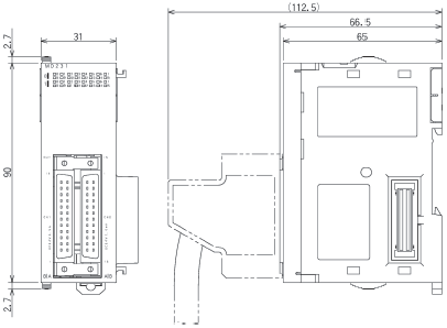
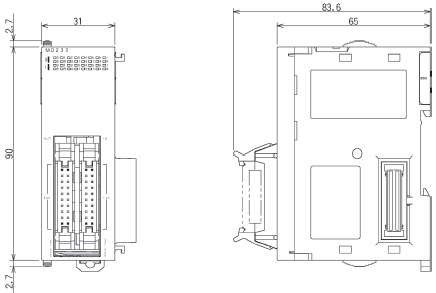
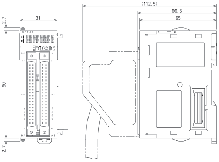
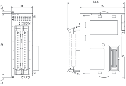
(Unit: mm)
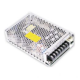
32-point Units (Mixed I/O Units)
With Fujitsu-compatible connector (24-pin × 2)
CJ1W-MD231
With MIL connector (20-pin × 2)
CJ1W-MD232
CJ1W-MD233
64-point Units (Mixed I/O Units)
With Fujitsu-compatible connector (40-pin × 2)
CJ1W-MD261
With MIL connector (40-pin × 2)
CJ1W-MD263
CJ1W-MD563
|
Catalog Name
|
Catalog Number
[size] |
Last Update
|
|---|---|---|
| – [3193KB] |
May 07, 2018 | |
| G126-E1-02 [2435KB] |
Apr 03, 2017 | |
| J217-E1-02 [1206KB] |
Jun 01, 2018 | |
| G129-E1-02 [950KB] |
Jun 01, 2018 |


Reviews
There are no reviews yet.