
Description
The adjustments made by skilled workers are automated using AI. The innovation of production sites has begun.
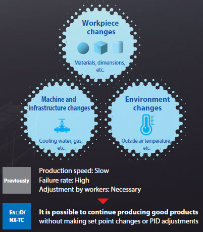
Optimal and automatic temperature control without human intervention easily achieves both productivity and quality.
Previous temperature controllers have not only required a long time for start-up settings and variation adjustments, it has also been difficult to make the optimal adjustments without having experience and intuition. There were therefore some effects on quality.
In response to this situation, OMRON developed temperature controllers that includes “adaptive control technology.”
This makes it possible to detect the changes in the status which will have an effect on quality and to automatically control the temperature so that the optimal state is always maintained, in the same way as a skilled worker would.
This frees production sites from troublesome start-up and adjustment work.
Causes of temperature variations on production lines
The answer was the industry’s first inclusion* of “adaptive control technology”
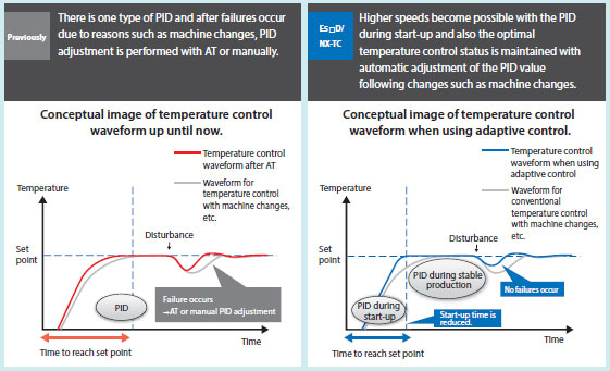
With the “adaptive control” incorporated into this product, the optimal PID value is calculated automatically for both the time of the start-up and for during stable production. Furthermore, it is possible to monitor the temperature control status of the machine to automatically adjust the PID value to obtain the optimal temperature control in response to changes such as workpiece changes and machine changes.
* According to an investigation by OMRON of general-purpose temperature controllers for FA as of March 2017.
[New value that supports advances in packaging machines] The sealing temperature is measured accurately and controlled automatically for packaging machines that can maintain quality even at higher speeds.
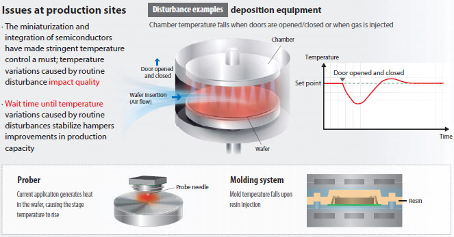
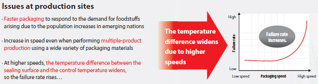
Issues at production sites
· Faster packaging to respond to the demand for foodstuffs arising due to the population increases in emerging nations
· Increase in speed even when performing multiple-product production using a wide variety of packaging materials
· At higher speeds, the temperature difference between the sealing surface and the control temperature widens, so the failure rate rises…
E5[]D/NX-TC solve the issues
The temperature of the sealing surface is stably controlled automatically with measurement of the sealing surface temperature and algorithms to suppress variations.
Even if the speed of the packaging process is increased, the difference between the sealing temperature and the control temperature is minimized to perform stable automatic control, so it is possible to realize faster production while maintaining the product quality.
This also contributes to the use of thinner packaging materials and to high precision control.
Even with the production of multiple products that require changes to the settings, automatic control reduces the work
Even in the production of multiple products, which hinders faster speeds because a change of packaging materials can mean that time is required to change the settings, the use of automatic control that has a small error in the sealing temperature enables a speedy response at production sites.
Control performance that achieves new value
The temperature error is minimized with a temperature sensor for packaging machines* and an algorithm for packaging machines (automatic filter adjustment function)
*Sold separately
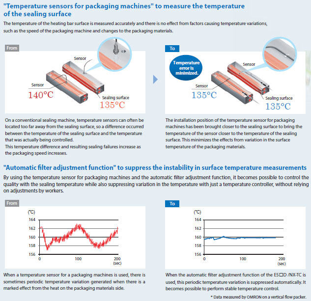
“Temperature sensors for packaging machines” to measure the temperature of the sealing surface
The temperature of the heating bar surface is measured accurately and there is no effect from factors causing temperature variations, such as the speed of the packaging machine and changes to the packaging materials.
“Automatic filter adjustment function” to suppress the instability in surface temperature measurements
By using the temperature sensor for packaging machines and the automatic filter adjustment function, it becomes possible to control the quality with the sealing temperature while also suppressing variation in the temperature with just a temperature controller, without relying on adjustments by workers.
[New value that supports advances in molding machines] Stable control of the temperature changes arising from faster speeds is performed automatically to realize molding machines that can maximize production capacity.
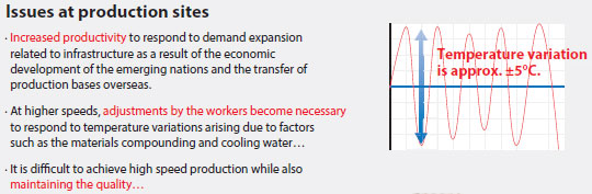
Issues at production sites
· Increased productivity to respond to demand expansion related to infrastructure as a result of the economic development of the emerging nations and the transfer of production bases overseas.
· At higher speeds, adjustments by the workers become necessary to respond to temperature variations arising due to factors such as the materials compounding and cooling water…
· It is difficult to achieve high speed production while also maintaining the quality…
E5[]D/NX-TC solve the issues
Temperature variations due to speed changes and changes in the status of machines are suppressed without adjustments by the workers
Stable control is achieved automatically by detecting the temperature variations on the heat generating parts of the material that occur when the speed of the extrusion molding machine is increased and by detecting the temperature variations due to variation in the cooling water. The work required for setting are also greatly reduced.
Also saves energy on the machine
The stable control reduces the wasteful use of energy on the heater by up to 40% compared with conventional machines.
* Data measured by OMRON on a water-cooled twin screw extrusion molding machine.
Control performance that achieves new value
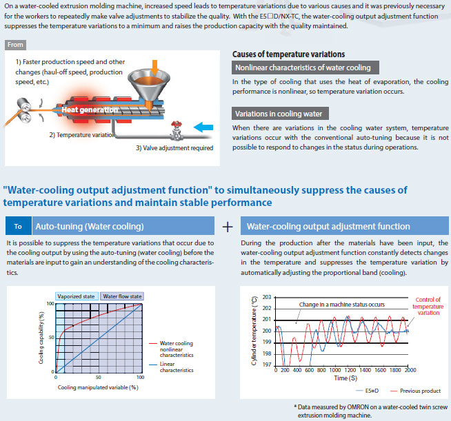
Temperature variations are minimized with an algorithm for molding machines (water-cooling output adjustment function)
On a water-cooled extrusion molding machine, increased speed leads to temperature variations due to various causes and it was previously necessary for the workers to repeatedly make valve adjustments to stabilize the quality.
With the E5[]D/NX-TC, the water-cooling output adjustment function suppresses the temperature variations to a minimum and raises the production capacity with the quality maintained.
“Water-cooling output adjustment function” to simultaneously suppress the causes of temperature variations and maintain stable performance
Push-In Plus Technology for Easy Wiring
E5[]D-B/NX-TC
Just Insert Wires: No Tools Required
Now you can use Push-In Plus technology to reduce the time and work involved in wiring.
Greatly Reduce Wiring Work
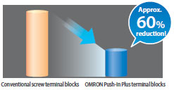
*Information for Push-In Plus and screw terminal blocks is based on OMRON’s actual measurement value data.
Easy to Insert
OMRON’s Push-In Plus technology are as easy as inserting to an earphone jack. They help reduce the work load and improve wiring quality.


Our shared Value Design for Panel (herein after referred to as “Value Design”) concept for the specifications of products used in control panels will create new value to our customer’s control panels.
International Standards
• The standards are abbreviated as follows: U: UL, U1: UL (Class I Division 2 Products for Hazardous Locations), C: CSA, UC: cULus, UC1: cULus (Class I Division 2 Products for Hazardous Locations), CU: cUL, N: NK, CE: EU Directives, RCM: Regulatory Compliance Mark, KC: KC Registration, and EAC: EAC Mark.
• Contact your OMRON representative for further details and applicable conditions for these standards.
Temperature Control Units
| Unit type |
Product name |
Specification | Model | Stand- ards |
|||||||
|---|---|---|---|---|---|---|---|---|---|---|---|
| Num- ber of chan- nels |
Input type |
Out- put |
Output capac- ity |
CT Input ca- pacity |
Con- trol type |
Con- ver- sion time |
I/O re- freshing method |
||||
| NX Series Temper- ature Control Unit |
Temper- ature Control Unit 2Ch type  |
2 Ch | Multi- input (Therm- ocouple and Resistance thermom- eter) |
Voltage output (for driving SSR) |
2 points |
2 points |
Standard Control |
50 m sec |
Free- Run refreshing |
NX-TC2405 | UC1, CE, RCM, KC, EAC |
| None | Standard Control |
NX-TC2406 | |||||||||
| Voltage output (for driving SSR) |
4 points |
None | Heating and Cooling Control |
NX-TC2407 | |||||||
| Linear current output |
2 points |
None | Standard Control |
NX-TC2408 | |||||||
| Temper- ature Control Unit 4Ch type  |
4 Ch | Voltage output (for driving SSR) |
4 points |
4 points |
Standard Control |
NX-TC3405 | |||||
| None | Standard Control |
NX-TC3406 | |||||||||
| Voltage output (for driving SSR) |
8 points |
None | Heating and Cooling Control |
NX-TC3407 | |||||||
| Linear current output |
4 points |
None | Standard Control |
NX-TC3408 | |||||||
Optional Products
| Product name | Specification | Model | Standards |
|---|---|---|---|
| Unit/Terminal Block Coding Pins | Pins for 10 Units (30 terminal block pins and 30 Unit pins) |
NX-AUX02 | — |
| Product name | Specification | Model | Standards |
|---|---|---|---|
| Current Transformer (CT) | Hole diameter: 5.8 mm | E54-CT1 | — |
| Hole diameter: 5.8 mm | E54-CT1L * | — | |
| Hole diameter: 12.0 mm | E54-CT3 | — | |
| Hole diameter: 12.0 mm | E54-CT3L * | — |
* Lead wires are included with these CTs. If UL certification is required, use these CTs.
Accessories
Not included.
General Specifications
| Item | Specification | |
|---|---|---|
| Enclosure | Mounted in a panel | |
| Grounding method | Ground to 100 Ω or less | |
| Operating environment |
Ambient operating temperature | 0 to 55°C |
| Ambient operating humidity | 10 to 95% RH (with no condensation or icing) | |
| Atmosphere | Must be free from corrosive gases. | |
| Ambient storage temperature | -25 to 70°C (with no condensation or icing) | |
| Altitude | 2,000 m max. | |
| Pollution degree | Pollution degree 2 or less: Conforms to JIS B 3502 and IEC 61131-2. | |
| Noise immunity | Conforms to IEC 61000-4-4, 2 kV (power supply line) | |
| Overvoltage category | Category II: Conforms to JIS B 3502 and IEC 61131-2. | |
| EMC immunity level | Zone B | |
| Vibration resistance | Conforms to IEC 60068-2-6. 5 to 8.4 Hz with amplitude of 3.5 mm, 8.4 to 150 Hz, acceleration of 9.8 m/s2 100 min each in X, Y, and Z directions (10 sweeps of 10 min each = 100 min total) |
|
| Shock resistance | Conforms to IEC 60068-2-27. 147 m/s2, 3 times each in X, Y, and Z directions |
|
| Insulation resistance | 20 MΩ min. between isolated circuits (at 100 VDC) | |
| Dielectric strength | 510 VAC between isolated circuits for 1 minute at a leakage current of 5 mA max. |
|
| Applicable standards * | cULus: Listed (UL 61010-2-201), ANSI/ISA 12.12.01, EU: EN 61131-2, RCM, KC: KC Registration, EAC |
|
* Ask your OMRON representative for the most recent applicable standards for each model.
List of Functions
| Function name | Description | Applicable units | |
|---|---|---|---|
| Free-Run Refreshing | With this I/O refreshing method, the refresh cycle of the NX bus and the I/O refresh cycles of the NX Units are asynchronous. |
All models | |
| Selecting Channel To Use | This function disables control processing, error detection, and output for unused channels. The conversion time for its own Unit will not be shortened even if errors are disabled. |
All models | |
| Input Functions |
Input Type Setting | This function sets the input type of the sensor connected to the temperature input. |
All models |
| Temperature Unit Setting (°C/°F) |
This function sets the temperature units for measured values to °C (Celsius) or °F (Fahrenheit). |
All models | |
| Decimal Point Position Setting |
This function sets the number of digits to be displayed after the decimal point for INT type measured values and set point parameters. |
All models | |
| Cold Junction Compensation Enable/Disable Setting |
This function enables or disables cold junction compensation using the cold junction sensor that is mounted on the terminal block when a thermocouple input is used. |
All models | |
| Temperature Input Correction |
This function corrects measured values. When there are variations in the sensor or when there is a difference in measured value from other measuring instruments. One-point correction and two-point correction methods are provided. |
All models | |
| Input Digital Filter | This function sets the time constant applied to the first-order lag operation filter so that the noise components mixed with the measured value are eliminated. |
All models | |
| Measuring the Ambient Temperature Around Terminals |
This function measures the temperature around the terminals of the Temperature Control Unit. |
All models | |
| Control Processing |
ON/OFF control | This control function uses a preset set point to turn off the control output when the temperature reaches the set point during control. |
All models |
| PID control | PID control is a combination of proportional (P) control, integral (I) control, and differential (D) control. It is a control function that feeds back the detected value to the set point so that they conform to each other. |
All models | |
| Heating/Cooling Control |
This function controls both heating and cooling. | Heating/cooling control type models |
|
| Run or Stop Controls | This function starts and stops temperature control. | All models | |
| Direct/Reverse Operation |
This function specifies direct or reverse operation. | All models | |
| Manual MV (Manual Manipulated Variable) |
This function outputs the specified manipulated variable during PID control. |
All models | |
| MV at Error (error MV) | This function outputs a fixed manipulated variable when a Sensor Disconnected Error occurs. |
All models | |
| MV Limit | This function adds a limit to the manipulated variable calculated by PID control and outputs it. |
All models | |
| Load Rejection MV | This function performs a preset output operation if the Temperature Control Unit connected to the CPU Unit cannot receive the output setting values from the CPU Unit due to an NX bus error or CPU watchdog timer error. This function performs a preset output operation if the Slave Terminal cannot receive the output setting values due to a communications error between the Temperature Control Unit and the Communications Coupler Unit host or due to an error on the NX bus. |
All models | |
| MV Branch | The manipulated variables calculated by the slope or offset are output to the branch-destination channel based on the manipulated variables of the branch-source channel. |
Standard control type models |
|
| Load Short-circuit Protection |
This function protects output circuits of the Temperature Control Unit when an external device connected to the control output is short-circuited. |
Models with voltage output (for driving SSR) |
|
| Tuning | AT (Autotuning) | This is a tuning method that derives the PID constant. This function automatically calculates the PID constant by the limit cycle method according to the characteristics of the control target. |
All models |
| Automatic Filter Adjustment |
This is a tuning method that automatically adjusts the input digital filter. This function is primarily for packing machines. It suppresses periodic temperature variations. |
Standard control type models |
|
| Water-cooling Output Adjustment |
This is a tuning method that automatically adjusts hunting. This function is primarily for water-cooled extruders. It suppresses temperature variations caused by the cooling water output. |
Heating/cooling control type models |
|
| Adaptive Control | This is a tuning method that can maintain high control performance by following system changes. This function maintains control performance even if temperature variation factors such as environmental change and equipment deterioration occur during a long-term equipment operation. |
Standard control type models |
|
| Notifying the Update of Tuning Parameters |
This function notifies that the Temperature Control Unit has automatically updated the parameters by tuning. |
All models | |
| Control Output |
Control Period | This function sets the period when the ON/OFF time ratio is changed for voltage output (for driving SSR) in time- proportional operation. |
Models with voltage output (for driving SSR) |
| Minimum Output ON/OFF Band |
This function specifies the minimum ON/OFF bands for the heating side control output or the cooling side control output. This function can be used to prevent deterioration of mechanical relays when mechanical relays are used in the actuators connected to the output terminals. |
Models with voltage output (for driving SSR) |
|
| Output Signal Range Setting |
This function sets the output signal range of the linear current output. You can specify 4 to 20 mA or 0 to 20 mA. |
Models with linear current output |
|
| Limiting Simultaneous Outputs |
This function limits the number of outputs that turn ON simultaneously by shifting the control period of each output and restricting the upper limit of the manipulated variable. You can set a delay between outputs, which allows delays in output device operation that can occur when outputs are switched. |
Standard control type models with voltage output (for driving SSR) |
|
| Error Detection |
Sensor Disconnection Detection |
This function detects disconnections in temperature sensors. It also detects that the measured value of the temperature sensor is outside the input indication range. |
All models |
| Heater Burnout Detection |
This function detects heater burnouts. A heater burnout is detected if the control output is ON and the heater current is equal to or less than the heater burnout detection current. |
Models with CT input |
|
| SSR Failure Detection | This function detects SSR failures. An SSR failure is detected if the control output is OFF and the leakage current is equal to or greater than the SSR failure detection current. An SSR failure is a failure that is caused by an SSR short-circuit. |
Models with CT input |
|
| Temperature alarms | Function for detecting a deviation or an error in the measured value as an alarm. Alarm operation corresponding to the use can be performed by selecting “Alarm type”. |
All models | |
| LBA (Loop Burnout Alarm) |
Function for detecting, as an alarm, the error location in the control loop when there is no change in the measured value while a control deviation equal to or more than the threshold value exists between the set point and the measured value. |
All models | |
Individual Specifications
Temperature Control Unit (2-Channel Type) NX-TC2405
| Unit name | Temperature Control Unit (2-Channel Type) |
Model | NX-TC2405 | ||
|---|---|---|---|---|---|
| Number of Channels | 2 channels | Control type | Standard control | ||
| Number of points per channel |
• Temperature input: 1 point per channel (2 points per unit) • CT Input: 1 point per channel (2 points per unit) • Control Output: 1 point per channel (2 points per unit) |
External connection terminal |
Screwless clamping terminal block (16 terminals) |
||
| I/O refreshing method | Free-Run Refreshing | ||||
| Indicators | TS indicator and output indicators  |
CT Input section |
CT current input range |
0 to 0.125 A | |
| Input resistance |
Approx. 2.7 Ω | ||||
| Connectable CTs |
E54-CT1, E54-CT3, E54-CT1L, and E54-CT3L |
||||
| Maximum heater current |
50 A AC | ||||
| Resolution | 0.1 A | ||||
| Overall accuracy (25°C) |
±5% (full scale) ±1 digit | ||||
| Influence of temperature (0 to 55°C) |
±2% (full scale) ±1 digit | ||||
| Conversion time |
50 ms/Unit | ||||
| Control Output section |
Control output type and number of control outputs per channel |
Voltage output for driving SSR, 1 point per channel |
|||
| Internal I/O common |
PNP | ||||
| Control Period | 0.1, 0.2, 0.5, 1 to 99s | ||||
| Manipulated variable |
-5 to +105% | ||||
| Sensor Input section |
Temperature sensor *1 |
• Thermocouple input: K, J, T, E, L, U, N, R, S, B, C/W, PL II • Platinum resistance thermometer input: Pt100 (three-wire), JPt100 (three- wire) |
Resolution | — | |
| Input conversion range |
±20°C of the input range *2 |
Rated Voltage | 24 VDC | ||
| Absolute maximum rating |
±130 mV | Operating Load Voltage Range |
15 to 28.8 VDC | ||
| Input impedance |
20 kΩ min. | Maximum load current |
21 mA/point, 42 mA/Unit | ||
| Resolution | 0.1°C max. | Maximum Inrush Current |
0.3 A/point max., 10 ms max. | ||
| Reference accuracy |
*3 | Allowable load resistance |
— | ||
| Temperature coefficient |
*3 | Leakage current |
0.1 mA max. | ||
| Cold junction compensation error |
±1.2°C *3 *4 | Residual voltage |
1.5 V max. | ||
| Input disconnection detection current |
Approx. 0.1 uA | Load Short- circuit Protection |
Provided | ||
| Input detection current |
0.25 mA | Output range | — | ||
| Effect of conductor resistance |
• Thermocouple input: 0.1°C/ Ω (100 Ω or less per conductor) • Platinum resistance thermometer input: 0.06°C/ Ω (20 Ω or less per conductor) |
Overall accuracy (25°C) |
— | ||
| Warm-up period |
30 minutes | Influence of temperature (0 to 55°C) |
— | ||
| Conversion time |
50 ms/Unit | ||||
| Dimensions | 12 mm (W) ×100 mm (H) × 71 mm (D) |
Isolation method | • Between sensor inputs and internal circuitry: Power = Transformer, Signal = Digital isolator • Between inputs: Power = Transformer, Signal = Digital isolator • No isolation between internal circuits and CT inputs • Between control output and internal circuit: Photocoupler • No isolation between control outputs |
||
| Insulation resistance | 20 MΩ min. between isolated circuits (at 100 VDC) |
Dielectric strength | 510 VAC between isolated circuits for 1 minute with a leakage current of 5 mA max. |
||
| I/O power supply method |
Supplied from the NX bus. | Current capacity of I/O power supply terminals |
IOG: 0.1 A max. per terminal | ||
| NX Unit power consumption |
• Connected to a CPU Unit 1.45 W max. • Connected to Communications Coupler Unit 1.10 W max. |
Current consumption from I/O power supply |
20 mA max. | ||
| Weight | 75 g max. | ||||
| Circuit configuration |  |
||||
| Installation orientation and restrictions |
Mounting orientation: • Connect to CPU unit Front mounting orientation is possible • Connect to communication coupler unit Six orientations are possible Limitation: |
||||
| Terminal connection diagram |
 |
||||
*2. + 20°C only for the following input type settings:
1: JPt100
3: JPt100
10: T
14: U
*3. For details, refer to the Reference Accuracy and Temperature Coefficient Table.
For thermocouple inputs, reference accuracy and cold junction compensation error are guaranteed for a set of a
Temperature Control Unit and a terminal block on which a cold junction sensor is mounted.
Be sure to use the terminal block and the Temperature Control Unit with the same calibration control number
together.
A calibration control number is displayed both on the terminal block and the Unit.
Make sure to return the terminal block to which a cold junction sensor is mounted and the Unit together.
*4. For details, refer to Cold Junction Compensation Error Specifications for Units That Take a Thermocouple Input Type.
Temperature Control Unit (2-Channel Type) NX-TC2406
| Unit name | Temperature Control Unit (2-Channel Type) |
Model | NX-TC2406 | ||
|---|---|---|---|---|---|
| Number of Channels | 2 channels | Control type | Standard control | ||
| Number of points per channel |
• Temperature input: 1 point per channel (2 points per unit) • CT input: None • Control Output: 1 point per channel (2 points per unit) |
External connection terminal |
Screwless clamping terminal block (16 terminals) |
||
| I/O refreshing method | Free-Run Refreshing | ||||
| Indicators | TS indicator and output indicators  |
CT Input section |
CT current input range |
— | |
| Input resistance |
— | ||||
| Connectable CTs |
— | ||||
| Maximum heater current |
— | ||||
| Resolution | — | ||||
| Overall accuracy (25°C) |
— | ||||
| Influence of temperature (0 to 55°C) |
— | ||||
| Conversion time |
— | ||||
| Control Output section |
Control output type and number of control outputs per channel |
Voltage output for driving SSR, 1 point per channel |
|||
| Internal I/O common |
PNP | ||||
| Control Period | 0.1, 0.2, 0.5, 1 to 99s | ||||
| Manipulated variable |
-5 to +105% | ||||
| Sensor Input section |
Temperature sensor *1 |
• Thermocouple input: K, J, T, E, L, U, N, R, S, B, C/W, PL II • Platinum resistance thermometer input: Pt100 (three-wire), JPt100 (three- wire) |
Resolution | — | |
| Input conversion range |
±20°C of the input range *2 |
Rated Voltage | 24 VDC | ||
| Absolute maximum rating |
±130 mV | Operating Load Voltage Range |
15 to 28.8 VDC | ||
| Input impedance |
20 kΩ min. | Maximum load current |
21 mA/point, 42 mA/Unit | ||
| Resolution | 0.1°C max. | Maximum Inrush Current |
0.3 A/point max., 10 ms max. | ||
| Reference accuracy |
*3 | Allowable load resistance |
— | ||
| Temperature coefficient |
*3 | Leakage current |
0.1 mA max. | ||
| Cold junction compensation error |
±1.2°C *3 *4 | Residual voltage |
1.5 V max. | ||
| Input disconnection detection current |
Approx. 0.1 uA | Load Short- circuit Protection |
Provided | ||
| Input detection current |
0.25 mA | Output range | — | ||
| Effect of conductor resistance |
• Thermocouple input: 0.1°C/ Ω (100 Ω or less per conductor) • Platinum resistance thermometer input: 0.06°C/ Ω (20 Ω or less per conductor) |
Overall accuracy (25°C) |
— | ||
| Warm-up period |
30 minutes | Influence of temperature (0 to 55°C) |
— | ||
| Conversion time |
50 ms/Unit | ||||
| Dimensions | 12 mm (W) ×100 mm (H) × 71 mm (D) |
Isolation method | • Between sensor inputs and internal circuitry: Power = Transformer, Signal = Digital isolator • Between inputs: Power = Transformer, Signal = Digital isolator • Between control output and internal circuit: Photocoupler • No isolation between control outputs |
||
| Insulation resistance | 20 MΩ min. between isolated circuits (at 100 VDC) |
Dielectric strength | 510 VAC between isolated circuits for 1 minute with a leakage current of 5 mA max. |
||
| I/O power supply method |
Supplied from the NX bus. | Current capacity of I/O power supply terminals |
IOG: 0.1 A max. per terminal | ||
| NX Unit power consumption |
• Connected to a CPU Unit 1.25 W max. • Connected to Communications Coupler Unit 0.95 W max. |
Current consumption from I/O power supply |
20 mA max. | ||
| Weight | 75 g max. | ||||
| Circuit configuration |  |
||||
| Installation orientation and restrictions |
Mounting orientation: • Connect to CPU unit Front mounting orientation is possible • Connect to communication coupler unit Six orientations are possible Limitation: |
||||
| Terminal connection diagram |
 |
||||
*2. + 20°C only for the following input type settings:
1: JPt100
3: JPt100
10: T
14: U
*3. For details, refer to the Reference Accuracy and Temperature Coefficient Table.
For thermocouple inputs, reference accuracy and cold junction compensation error are guaranteed for a set of a
Temperature Control Unit and a terminal block on which a cold junction sensor is mounted.
Be sure to use the terminal block and the Temperature Control Unit with the same calibration control number
together.
A calibration control number is displayed both on the terminal block and the Unit.
Make sure to return the terminal block to which a cold junction sensor is mounted and the Unit together.
*4. For details, refer to Cold Junction Compensation Error Specifications for Units That Take a Thermocouple Input Type.
Temperature Control Unit (2-Channel Type) NX-TC2407
| Unit name | Temperature Control Unit (2-Channel Type) |
Model | NX-TC2407 | ||
|---|---|---|---|---|---|
| Number of Channels | 2 channels | Control type | Heating and cooling control | ||
| Number of points per channel |
• Temperature input: 1 point per channel (2 points per unit) • CT input: None • Control Output: 2 point per channel (4 points per unit) |
External connection terminal |
Screwless clamping terminal block (16 terminals) |
||
| I/O refreshing method | Free-Run Refreshing | ||||
| Indicators | TS indicator and output indicators  |
CT Input section |
CT current input range |
— | |
| Input resistance |
— | ||||
| Connectable CTs |
— | ||||
| Maximum heater current |
— | ||||
| Resolution | — | ||||
| Overall accuracy (25°C) |
— | ||||
| Influence of temperature (0 to 55°C) |
— | ||||
| Conversion time |
— | ||||
| Control Output section |
Control output type and number of control outputs per channel |
Voltage output for driving SSR, 2 point per channel |
|||
| Internal I/O common |
PNP | ||||
| Control Period | 0.1, 0.2, 0.5, 1 to 99s | ||||
| Manipulated variable |
• Heating: 0 to +105% • Cooling: 0 to +105% |
||||
| Sensor Input section |
Temperature sensor *1 |
Thermocouple input: K, J, T, E, L, U, N, R, S, B, C/W, PL II Platinum resistance thermometer input: Pt100 (three-wire), JPt100 (three- wire) |
Resolution | — | |
| Input conversion range |
±20°C of the input range *2 |
Rated Voltage | 24 VDC | ||
| Absolute maximum rating |
±130 mV | Operating Load Voltage Range |
15 to 28.8 VDC | ||
| Input impedance |
20 kΩ min. | Maximum load current |
21 mA/point, 84 mA/Unit | ||
| Resolution | 0.1°C max. | Maximum Inrush Current |
0.3 A/point max., 10 ms max. | ||
| Reference accuracy |
*3 | Allowable load resistance |
— | ||
| Temperature coefficient |
*3 | Leakage current |
0.1 mA max. | ||
| Cold junction compensation error |
±1.2°C *3 *4 | Residual voltage |
1.5 V max. | ||
| Input disconnection detection current |
Approx. 0.1 uA | Load Short- circuit Protection |
Provided | ||
| Input detection current |
0.25 mA | Output range | — | ||
| Effect of conductor resistance |
• Thermocouple input: 0.1°C/ Ω (100 Ω or less per conductor) • Platinum resistance thermometer input: 0.06°C/ Ω (20 Ω or less per conductor) |
Overall accuracy (25°C) |
— | ||
| Warm-up period |
30 minutes | Influence of temperature (0 to 55°C) |
— | ||
| Conversion time |
50 ms/Unit | ||||
| Dimensions | 12 mm (W) ×100 mm (H) × 71 mm (D) |
Isolation method | • Between sensor inputs and internal circuitry: Power = Transformer, Signal = Digital isolator • Between inputs: Power = Transformer, Signal = Digital isolator • Between control output and internal circuit: Photocoupler • No isolation between control outputs |
||
| Insulation resistance | 20 MΩ min. between isolated circuits (at 100 VDC) |
Dielectric strength | 510 VAC between isolated circuits for 1 minute with a leakage current of 5 mA max. |
||
| I/O power supply method |
Supplied from the NX bus. | Current capacity of I/O power supply terminals |
IOG: 0.1 A max. per terminal | ||
| NX Unit power consumption |
• Connected to a CPU Unit 1.30 W max. • Connected to Communications Coupler Unit 1.00 W max. |
Current consumption from I/O power supply |
20 mA max. | ||
| Weight | 75 g max. | ||||
| Circuit configuration |  |
||||
| Installation orientation and restrictions |
Mounting orientation: • Connect to CPU unit Front mounting orientation is possible • Connect to communication coupler unit Six orientations are possible Limitation: |
||||
| Terminal connection diagram |
 |
||||
*2. + 20°C only for the following input type settings:
1: JPt100
3: JPt100
10: T
14: U
*3. For details, refer to the Reference Accuracy and Temperature Coefficient Table.
For thermocouple inputs, reference accuracy and cold junction compensation error are guaranteed for a set of a
Temperature Control Unit and a terminal block on which a cold junction sensor is mounted.
Be sure to use the terminal block and the Temperature Control Unit with the same calibration control number
together.
A calibration control number is displayed both on the terminal block and the Unit.
Make sure to return the terminal block to which a cold junction sensor is mounted and the Unit together.
*4. For details, refer to Cold Junction Compensation Error Specifications for Units That Take a Thermocouple Input Type.
Temperature Control Unit (2-Channel Type) NX-TC2408
| Unit name | Temperature Control Unit (2-Channel Type) |
Model | NX-TC2408 | ||
|---|---|---|---|---|---|
| Number of Channels | 2 channels | Control type | Standard control | ||
| Number of points per channel |
• Temperature input: 1 point per channel (2 points per unit) • CT input: None • Control Output: 1 point per channel (2 points per unit) |
External connection terminal |
Screwless clamping terminal block (16 terminals) |
||
| I/O refreshing method | Free-Run Refreshing | ||||
| Indicators | TS indicator and output indicators  |
CT Input section |
CT current input range |
— | |
| Input resistance |
— | ||||
| Connectable CTs |
— | ||||
| Maximum heater current |
— | ||||
| Resolution | — | ||||
| Overall accuracy (25°C) |
— | ||||
| Influence of temperature (0 to 55°C) |
— | ||||
| Conversion time |
— | ||||
| Control Output section |
Control output type and number of control outputs per channel |
Linear current output, one output per channel |
|||
| Internal I/O common |
— | ||||
| Control Period | — | ||||
| Manipulated variable |
-5 to +105% | ||||
| Sensor Input section |
Temperature sensor *1 |
• Thermocouple input: K, J, T, E, L, U, N, R, S, B, C/W, PL II • Platinum resistance thermometer input: Pt100 (three-wire), JPt100 (three- wire) |
Resolution | 1/10,000 | |
| Input conversion range |
±20°C of the input range *2 |
Rated Voltage | 24 VDC | ||
| Absolute maximum rating |
±130 mV | Operating Load Voltage Range |
15 to 28.8 VDC | ||
| Input impedance |
20 kΩ min. | Maximum load current |
— | ||
| Resolution | 0.1°C max. | Maximum Inrush Current |
— | ||
| Reference accuracy |
*3 | Allowable load resistance |
350 Ω or less, or greater than 350 Ω but no more than 600 Ω *4 |
||
| Temperature coefficient |
*3 | Leakage current |
— | ||
| Cold junction compensation error |
±1.2°C *3 *5 | Residual voltage |
— | ||
| Input disconnection detection current |
Approx. 0.1 uA | Load Short- circuit Protection |
— | ||
| Input detection current |
0.25 mA | Output range | 0 to 20 mA, 4 to 20 mA | ||
| Effect of conductor resistance |
• Thermocouple input: 0.1°C/ Ω (100 Ω or less per conductor) • Platinum resistance thermometer input: 0.06°C/ Ω (20 Ω or less per conductor) |
Overall accuracy (25°C) |
±0.3% of full scale, but 1% of full scale at 0 to 4 mA of 0 to 20 mA range |
||
| Warm-up period |
30 minutes | Influence of temperature (0 to 55°C) |
±0.3% (full scale) | ||
| Conversion time |
50 ms/Unit | ||||
| Dimensions | 12 mm (W) ×100 mm (H) × 71 mm (D) |
Isolation method | • Between sensor inputs and internal circuitry: Power = Transformer, Signal = Digital isolator • Between inputs: Power = Transformer, Signal = Digital isolator • Between control output and internal circuit: Photocoupler • No isolation between control outputs |
||
| Insulation resistance | 20 MΩ min. between isolated circuits (at 100 VDC) |
Dielectric strength | 510 VAC between isolated circuits for 1 minute with a leakage current of 5 mA max. |
||
| I/O power supply method |
Supplied from the NX bus. | Current capacity of I/O power supply terminals |
IOG: 0.1 A max. per terminal | ||
| NX Unit power consumption |
• Connected to a CPU Unit 1.25 W max. • Connected to Communications Coupler Unit 0.95 W max. |
Current consumption from I/O power supply |
20 mA max. | ||
| Weight | 75 g max. | ||||
| Circuit configuration |  |
||||
| Installation orientation and restrictions |
Mounting orientation: • Connect to CPU unit Front mounting orientation is possible • Connect to communication coupler unit Six orientations are possible Limitation: |
||||
| Terminal connection diagram |
 |
||||
*2. + 20°C only for the following input type settings:
1: JPt100
3: JPt100
10: T
14: U
*3. For details, refer to the Reference Accuracy and Temperature Coefficient Table.
For thermocouple inputs, reference accuracy and cold junction compensation error are guaranteed for a set of a
Temperature Control Unit and a terminal block on which a cold junction sensor is mounted.
Be sure to use the terminal block and the Temperature Control Unit with the same calibration control number
together.
A calibration control number is displayed both on the terminal block and the Unit.
Make sure to return the terminal block to which a cold junction sensor is mounted and the Unit together.
*4. To use an allowable load resistance greater than 350 Ω but not exceeding 600 Ω, SHT1 and SHT2 must be shorted
with a shorting cable.
For details, refer to the NX-series Temperature Control Units User’s Manual (Cat. No. W523).
*5. For details, refer to Cold Junction Compensation Error Specifications for Units That Take a Thermocouple Input Type.
Temperature Control Unit (4-Channel Type) NX-TC3405
| Unit name | Temperature Control Unit (4-Channel Type) |
Model | NX-TC3405 | ||
|---|---|---|---|---|---|
| Number of Channels | 4 channels | Control type | Standard control | ||
| Number of points per channel |
• Temperature input: 1 point per channel (4 points per unit) • CT Input: 1 point per channel (4 points per unit) • Control Output: 1 point per channel (4 points per unit) |
External connection terminal |
Screwless clamping terminal block (16 terminals x 2) |
||
| I/O refreshing method | Free-Run Refreshing | ||||
| Indicators | TS indicator and output indicators  |
CT Input section |
CT current input range |
0 to 0.125 A | |
| Input resistance |
Approx. 2.7 Ω | ||||
| Connectable CTs |
E54-CT1, E54-CT3, E54-CT1L, and E54-CT3L |
||||
| Maximum heater current |
50 A AC | ||||
| Resolution | 0.1 A | ||||
| Overall accuracy (25°C) |
±5% (full scale) ±1 digit | ||||
| Influence of temperature (0 to 55°C) |
±2% (full scale) ±1 digit | ||||
| Conversion time |
50 ms/Unit | ||||
| Control Output section |
Control output type and number of control outputs per channel |
Voltage output for driving SSR, 1 point per channel |
|||
| Internal I/O common |
PNP | ||||
| Control Period | 0.1, 0.2, 0.5, 1 to 99s | ||||
| Manipulated variable |
-5 to +105% | ||||
| Sensor Input section |
Temperature sensor *1 |
• Thermocouple input: K, J, T, E, L, U, N, R, S, B, C/W, PL II • Platinum resistance thermometer input: Pt100 (three-wire), JPt100 (three- wire) |
Resolution | — | |
| Input conversion range |
±20°C of the input range *2 |
Rated Voltage | 24 VDC | ||
| Absolute maximum rating |
±130 mV | Operating Load Voltage Range |
15 to 28.8 VDC | ||
| Input impedance |
20 kΩ min. | Maximum load current |
21 mA/point, 84 mA/Unit | ||
| Resolution | 0.1°C max. | Maximum Inrush Current |
0.3 A/point max., 10 ms max. | ||
| Reference accuracy |
*3 | Allowable load resistance |
— | ||
| Temperature coefficient |
*3 | Leakage current |
0.1 mA max. | ||
| Cold junction compensation error |
±1.2°C *3 *4 | Residual voltage |
1.5 V max. | ||
| Input disconnection detection current |
Approx. 0.1 uA | Load Short- circuit Protection |
Provided | ||
| Input detection current |
0.25 mA | Output range | — | ||
| Effect of conductor resistance |
• Thermocouple input: 0.1°C/ Ω (100 Ω or less per conductor) • Platinum resistance thermometer input: 0.06°C/ Ω (20 Ω or less per conductor) |
Overall accuracy (25°C) |
— | ||
| Warm-up period |
30 minutes | Influence of temperature (0 to 55°C) |
— | ||
| Conversion time |
50 ms/Unit | ||||
| Dimensions | 24 mm (W) ×100 mm (H) × 71 mm (D) |
Isolation method | • Between sensor inputs and internal circuitry: Power = Transformer, Signal = Digital isolator • Between inputs: Power = Transformer, Signal = Digital isolator • No isolation between internal circuits and CT inputs • Between control output and internal circuit: Photocoupler • No isolation between control outputs |
||
| Insulation resistance | 20 MΩ min. between isolated circuits (at 100 VDC) |
Dielectric strength | 510 VAC between isolated circuits for 1 minute with a leakage current of 5 mA max. |
||
| I/O power supply method |
Supplied from the NX bus. | Current capacity of I/O power supply terminals |
IOG: 0.1 A max. per terminal | ||
| NX Unit power consumption |
• Connected to a CPU Unit 1.80 W max. • Connected to Communications Coupler Unit 1.35 W max. |
Current consumption from I/O power supply |
20 mA max. | ||
| Weight | 140 g max. | ||||
| Circuit configuration |  |
||||
| Installation orientation and restrictions |
Mounting orientation: • Connect to CPU unit Front mounting orientation is possible • Connect to communication coupler unit Six orientations are possible Limitation: |
||||
| Terminal connection diagram |
 |
||||
*2. + 20°C only for the following input type settings:
1: JPt100
3: JPt100
10: T
14: U
*3. For details, refer to the Reference Accuracy and Temperature Coefficient Table.
For thermocouple inputs, reference accuracy and cold junction compensation error are guaranteed for a set of a
Temperature Control Unit and a terminal block on which a cold junction sensor is mounted.
Be sure to use the terminal block and the Temperature Control Unit with the same calibration control number
together.
A calibration control number is displayed both on the terminal block and the Unit.
In order to distinguish left and right terminal blocks, each terminal block has either a letter “L” (left side) or “R” (right
side) appended at the end of a calibration control number.
Make sure to return the terminal block to which a cold junction sensor is mounted and the Unit together.
*4. For details, refer to Cold Junction Compensation Error Specifications for Units That Take a Thermocouple Input Type.
Temperature Control Unit (4-Channel Type) NX-TC3406
| Unit name | Temperature Control Unit (4-Channel Type) |
Model | NX-TC3406 | ||
|---|---|---|---|---|---|
| Number of Channels | 4 channels | Control type | Standard control | ||
| Number of points per channel |
• Temperature input: 1 point per channel (4 points per unit) • CT input: None • Control Output: 1 point per channel (4 points per unit) |
External connection terminal |
Screwless clamping terminal block (16 terminals x 2) |
||
| I/O refreshing method | Free-Run Refreshing | ||||
| Indicators | TS indicator and output indicators  |
CT Input section |
CT current input range |
— | |
| Input resistance |
— | ||||
| Connectable CTs |
— | ||||
| Maximum heater current |
— | ||||
| Resolution | — | ||||
| Overall accuracy (25°C) |
— | ||||
| Influence of temperature (0 to 55°C) |
— | ||||
| Conversion time |
— | ||||
| Control Output section |
Control output type and number of control outputs per channel |
Voltage output for driving SSR, 1 point per channel |
|||
| Internal I/O common |
PNP | ||||
| Control Period | 0.1, 0.2, 0.5, 1 to 99s | ||||
| Manipulated variable |
-5 to +105% | ||||
| Sensor Input section |
Temperature sensor *1 |
• Thermocouple input: K, J, T, E, L, U, N, R, S, B, C/W, PL II • Platinum resistance thermometer input: Pt100 (three-wire), JPt100 (three- wire) |
Resolution | — | |
| Input conversion range |
±20°C of the input range *2 |
Rated Voltage | 24 VDC | ||
| Absolute maximum rating |
±130 mV | Operating Load Voltage Range |
15 to 28.8 VDC | ||
| Input impedance |
20 kΩ min. | Maximum load current |
21 mA/point, 84 mA/Unit | ||
| Resolution | 0.1°C max. | Maximum Inrush Current |
0.3 A/point max., 10 ms max. | ||
| Reference accuracy |
*3 | Allowable load resistance |
— | ||
| Temperature coefficient |
*3 | Leakage current |
0.1 mA max. | ||
| Cold junction compensation error |
±1.2°C *3 *4 | Residual voltage |
1.5 V max. | ||
| Input disconnection detection current |
Approx. 0.1 uA | Load Short- circuit Protection |
Provided | ||
| Input detection current |
0.25 mA | Output range | — | ||
| Effect of conductor resistance |
• Thermocouple input: 0.1°C/ Ω (100 Ω or less per conductor) • Platinum resistance thermometer input: 0.06°C/ Ω (20 Ω or less per conductor) |
Overall accuracy (25°C) |
— | ||
| Warm-up period |
30 minutes | Influence of temperature (0 to 55°C) |
— | ||
| Conversion time |
50 ms/Unit | ||||
| Dimensions | 24 mm (W) ×100 mm (H) × 71 mm (D) |
Isolation method | • Between sensor inputs and internal circuitry: Power = Transformer, Signal = Digital isolator • Between inputs: Power = Transformer, Signal = Digital isolator • Between control output and internal circuit: Photocoupler • No isolation between control outputs |
||
| Insulation resistance | 20 MΩ min. between isolated circuits (at 100 VDC) |
Dielectric strength | 510 VAC between isolated circuits for 1 minute with a leakage current of 5 mA max. |
||
| I/O power supply method |
Supplied from the NX bus. | Current capacity of I/O power supply terminals |
IOG: 0.1 A max. per terminal | ||
| NX Unit power consumption |
• Connected to a CPU Unit 1.70 W max. • Connected to Communications Coupler Unit 1.25 W max. |
Current consumption from I/O power supply |
20 mA max. | ||
| Weight | 140 g max. | ||||
| Circuit configuration |  |
||||
| Installation orientation and restrictions |
Mounting orientation: • Connect to CPU unit Front mounting orientation is possible • Connect to communication coupler unit Six orientations are possible Limitation: |
||||
| Terminal connection diagram |
 |
||||
*2. + 20°C only for the following input type settings:
1: JPt100
3: JPt100
10: T
14: U
*3. For details, refer to the Reference Accuracy and Temperature Coefficient Table.
For thermocouple inputs, reference accuracy and cold junction compensation error are guaranteed for a set of a
Temperature Control Unit and a terminal block on which a cold junction sensor is mounted.
Be sure to use the terminal block and the Temperature Control Unit with the same calibration control number
together.
A calibration control number is displayed both on the terminal block and the Unit.
In order to distinguish left and right terminal blocks, each terminal block has either a letter “L” (left side) or “R” (right
side) appended at the end of a calibration control number.
Make sure to return the terminal block to which a cold junction sensor is mounted and the Unit together.
*4. For details, refer to Cold Junction Compensation Error Specifications for Units That Take a Thermocouple Input Type.
Temperature Control Unit (4-Channel Type) NX-TC3407
| Unit name | Temperature Control Unit (4-Channel Type) |
Model | NX-TC3407 | ||
|---|---|---|---|---|---|
| Number of Channels | 4 channels | Control type | heating and cooling control | ||
| Number of points per channel |
• Temperature input: 1 point per channel (4 points per unit) • CT input: None • Control Output: 2 point per channel (8 points per unit) |
External connection terminal |
Screwless clamping terminal block (16 terminals x 2) |
||
| I/O refreshing method | Free-Run Refreshing | ||||
| Indicators | TS indicator and output indicators  |
CT Input section |
CT current input range |
— | |
| Input resistance |
— | ||||
| Connectable CTs |
— | ||||
| Maximum heater current |
— | ||||
| Resolution | — | ||||
| Overall accuracy (25°C) |
— | ||||
| Influence of temperature (0 to 55°C) |
— | ||||
| Conversion time |
— | ||||
| Control Output section |
Control output type and number of control outputs per channel |
Voltage output for driving SSR, 2 point per channel |
|||
| Internal I/O common |
PNP | ||||
| Control Period | 0.1, 0.2, 0.5, 1 to 99s | ||||
| Manipulated variable |
• Heating: 0 to +105% • Cooling: 0 to +105% |
||||
| Sensor Input section |
Temperature sensor *1 |
• Thermocouple input: K, J, T, E, L, U, N, R, S, B, C/W, PL II • Platinum resistance thermometer input: Pt100 (three-wire), JPt100 (three- wire) |
Resolution | — | |
| Input conversion range |
±20°C of input range *2 |
Rated Voltage | 24 VDC | ||
| Absolute maximum rating |
±130 mV | Operating Load Voltage Range |
15 to 28.8 VDC | ||
| Input impedance |
20 kΩ min. | Maximum load current |
21 mA/point, 168 mA/Unit | ||
| Resolution | 0.1°C max. | Maximum Inrush Current |
0.3 A/point max., 10 ms max. | ||
| Reference accuracy |
*3 | Allowable load resistance |
— | ||
| Temperature coefficient |
*3 | Leakage current |
0.1 mA max. | ||
| Cold junction compensation error |
±1.2°C *3 *4 | Residual voltage |
1.5 V max. | ||
| Input disconnection detection current |
Approx. 0.1 uA | Load Short- circuit Protection |
Provided | ||
| Input detection current |
0.25 mA | Output range | — | ||
| Effect of conductor resistance |
• Thermocouple input: 0.1°C/ Ω (100 Ω or less per conductor) • Platinum resistance thermometer input: 0.06°C/ Ω (20 Ω or less per conductor) |
Overall accuracy (25°C) |
— | ||
| Warm-up period |
30 minutes | Influence of temperature (0 to 55°C) |
— | ||
| Conversion time |
50 ms/Unit | ||||
| Dimensions | 24 mm (W) ×100 mm (H) × 71 mm (D) |
Isolation method | • Between sensor inputs and internal circuitry: Power = Transformer, Signal = Digital isolator • Between inputs: Power = Transformer, Signal = Digital isolator • Between control output and internal circuit: Photocoupler • No isolation between control outputs |
||
| Insulation resistance | 20 MΩ min. between isolated circuits (at 100 VDC) |
Dielectric strength | 510 VAC between isolated circuits for 1 minute with a leakage current of 5 mA max. |
||
| I/O power supply method |
Supplied from the NX bus. | Current capacity of I/O power supply terminals |
IOG: 0.1 A max. per terminal | ||
| NX Unit power consumption |
• Connected to a CPU Unit 1.75 W max. • Connected to Communications Coupler Unit 1.30 W max. |
Current consumption from I/O power supply |
20 mA max. | ||
| Weight | 140 g max. | ||||
| Circuit configuration |  |
||||
| Installation orientation and restrictions |
Mounting orientation: • Connect to CPU unit Front mounting orientation is possible • Connect to communication coupler unit Six orientations are possible Limitation: |
||||
| Terminal connection diagram |
 |
||||
*2. + 20°C only for the following input type settings:
1: JPt100
3: JPt100
10: T
14: U
*3. For details, refer to the Reference Accuracy and Temperature Coefficient Table.
For thermocouple inputs, reference accuracy and cold junction compensation error are guaranteed for a set of a
Temperature Control Unit and a terminal block on which a cold junction sensor is mounted.
Be sure to use the terminal block and the Temperature Control Unit with the same calibration control number
together.
A calibration control number is displayed both on the terminal block and the Unit.
In order to distinguish left and right terminal blocks, each terminal block has either a letter “L” (left side) or “R” (right
side) appended at the end of a calibration control number.
Make sure to return the terminal block to which a cold junction sensor is mounted and the Unit together.
*4. For details, refer to Cold Junction Compensation Error Specifications for Units That Take a Thermocouple Input Type.
Temperature Control Unit (4-Channel Type) NX-TC3408
| Unit name | Temperature Control Unit (4-Channel Type) |
Model | NX-TC3408 | ||
|---|---|---|---|---|---|
| Number of Channels | 4 channels | Control type | Standard control | ||
| Number of points per channel |
• Temperature input: 1 point per channel (4 points per unit) • CT input: None • Control Output: 1 point per channel (4 points per unit) |
External connection terminal |
Screwless clamping terminal block (16 terminals x 2) |
||
| I/O refreshing method | Free-Run Refreshing | ||||
| Indicators | TS indicator and output indicators  |
CT Input section |
CT current input range |
— | |
| Input resistance |
— | ||||
| Connectable CTs |
— | ||||
| Maximum heater current |
— | ||||
| Resolution | — | ||||
| Overall accuracy (25°C) |
— | ||||
| Influence of temperature (0 to 55°C) |
— | ||||
| Conversion time |
— | ||||
| Control Output section |
Control output type and number of control outputs per channel |
Linear current output, one output per channel |
|||
| Internal I/O common |
— | ||||
| Control Period | — | ||||
| Manipulated variable |
-5 to +105% | ||||
| Sensor Input section |
Temperature sensor *1 |
• Thermocouple input: K, J, T, E, L, U, N, R, S, B, C/W, PL II • Platinum resistance thermometer input: Pt100 (three-wire), JPt100 (three- wire) |
Resolution | 1/10,000 | |
| Input conversion range |
±20°C of the input range *2 |
Rated Voltage | 24 VDC | ||
| Absolute maximum rating |
±130 mV | Operating Load Voltage Range |
15 to 28.8 VDC | ||
| Input impedance |
20 kΩ min. | Maximum load current |
— | ||
| Resolution | 0.1°C max. | Maximum Inrush Current |
— | ||
| Reference accuracy |
*3 | Allowable load resistance |
350 Ω or less, or greater than 350 Ω but no more than 600 Ω *4 |
||
| Temperature coefficient |
*3 | Leakage current |
— | ||
| Cold junction compensation error |
±1.2°C *3 *5 | Residual voltage |
— | ||
| Input disconnection detection current |
Approx. 0.1 uA | Load Short- circuit Protection |
— | ||
| Input detection current |
0.25 mA | Output range | 0 to 20 mA, 4 to 20 mA | ||
| Effect of conductor resistance |
• Thermocouple input: 0.1°C/ Ω (100 Ω or less per conductor) • Platinum resistance thermometer input: 0.06°C/ Ω (20 Ω or less per conductor) |
Overall accuracy (25°C) |
±0.3% of full scale, but 1% of full scale at 0 to 4 mA of 0 to 20 mA range |
||
| Warm-up period |
30 minutes | Influence of temperature (0 to 55°C) |
±0.3% (full scale) | ||
| Conversion time |
50 ms/Unit | ||||
| Dimensions | 24 mm (W) ×100 mm (H) × 71 mm (D) |
Isolation method | • Between sensor inputs and internal circuitry: Power = Transformer, Signal = Digital isolator • Between inputs: Power = Transformer, Signal = Digital isolator • Between control output and internal circuit: Photocoupler • No isolation between control outputs |
||
| Insulation resistance | 20 MΩ min. between isolated circuits (at 100 VDC) |
Dielectric strength | 510 VAC between isolated circuits for 1 minute with a leakage current of 5 mA max. |
||
| I/O power supply method |
Supplied from the NX bus. | Current capacity of I/O power supply terminals |
IOG: 0.1 A max. per terminal | ||
| NX Unit power consumption |
• Connected to a CPU Unit 1.65 W max. • Connected to Communications Coupler Unit 1.25 W max. |
Current consumption from I/O power supply |
30 mA max. | ||
| Weight | 140 g max. | ||||
| Circuit configuration |  |
||||
| Installation orientation and restrictions |
Mounting orientation: • Connect to CPU unit Front mounting orientation is possible • Connect to communication coupler unit Six orientations are possible Limitation: |
||||
| Terminal connection diagram |
 |
||||
*2. + 20°C only for the following input type settings:
1: JPt100
3: JPt100
10: T
14: U
*3. For details, refer to the Reference Accuracy and Temperature Coefficient Table.
For thermocouple inputs, reference accuracy and cold junction compensation error are guaranteed for a set of a
Temperature Control Unit and a terminal block on which a cold junction sensor is mounted.
Be sure to use the terminal block and the Temperature Control Unit with the same calibration control number
together.
A calibration control number is displayed both on the terminal block and the Unit.
In order to distinguish left and right terminal blocks, each terminal block has either a letter “L” (left side) or “R” (right
side) appended at the end of a calibration control number.
Make sure to return the terminal block to which a cold junction sensor is mounted and the Unit together.
*4. To use an allowable load resistance greater than 350 Ω but not exceeding 600 Ω, either SHT1 and SHT2, or SHT3 and
SHT4 must be shorted with a shorting cable.
For details, refer to the NX-series Temperature Control Units User’s Manual (Cat. No. W523).
*5. For details, refer to Cold Junction Compensation Error Specifications for Units That Take a Thermocouple Input Type.
Input types
The settings are shown in the following table.
| Setting name *1 | Display of support software |
Description | Default | Setting range |
Unit | Change application timing |
|---|---|---|---|---|---|---|
| Ch[] input type | Ch[] Input Type | Sets the input type of sensors connected to temperature input. |
5: K -200 to 1300°C |
*2 | No | After unit restart |
*1.[] represents the channel number.
*2. The setting range is as follows:
| Set values |
Input types | Input indication range | Remarks | |
|---|---|---|---|---|
| Sensor | Input setting range | |||
| 0 | Pt100 | -200 to 850°C/-300 to 1500°F | -220 to 870°C/-340 to 1540°F | Resistance thermometer |
| 1 | Pt100 | -199.9 to 500.0°C/-199.9 to 900.0°F | -219.9 to 520.0°C/-239.9 to 940.0°F | |
| 2 | Pt100 | -0.0 to 100.0°C/0.0 to 210.0°F | -20.0 to 120.0°C/-40.0 to 250.0°F | |
| 3 | JPt100 | -199.9 to 500.0°C/-199.9 to 900.0°F | -219.9 to 520.0°C/-239.9 to 940.0°F | |
| 4 | JPt100 | -0.0 to 100.0°C/0.0 to 210.0°F | -20.0 to 120.0°C/-40.0 to 250.0°F | |
| 5 | K | -200 to 1300°C/-300 to 2300°F | -220 to 1320°C/-340 to 2340°F | Thermocouple |
| 6 | K | -20.0 to 500.0°C/0.0 to 900.0°F | -40.0 to 520.0°C/-40.0 to 940.0°F | |
| 7 | J | -100 to 850°C/-100.0 to 1500°F | -120 to 870°C/-140 to 1540°F | |
| 8 | J | -20.0 to 400.0°C/0.0 to 750.0°F | -40.0 to 420.0°C/-40.0 to 790.0°F | |
| 9 | T | -200 to 400°C/-300 to 700°F | -220 to 420°C/-340 to 740°F | |
| 10 | T | -199.9 to 400.0°C/-199.9 to 700.0°F | -219.9 to 420.0°C/-239.9 to 740°F | |
| 11 | E | -200 to 600°C/-300 to 1100°F | -220 to 620°C/-340 to 1140°F | |
| 12 | L | -100 to 850°C/-100 to 1500°F | -120 to 870°C/-140 to 1540°F | |
| 13 | U | -200 to 400°C/-300 to 700°F | -220 to 420°C/-340 to 740°F | |
| 14 | U | -199.9 to 400.0°C/-199.9 to 700.0°F | -219.9 to 420.0°C/-239.9 to 740°F | |
| 15 | N | -200 to 1300°C/-300 to 2300°F | -220 to 1320°C/-340 to 2340°F | |
| 16 | R | 0 to 1700°C/0 to 3000°F | -20 to 1720°C/-40 to 3040°F | |
| 17 | S | 0 to 1700°C/0 to 3000°F | -20 to 1720°C/-40 to 3040°F | |
| 18 | B | 0 to 1800°C/0 to 3200°F | -20 to 1820°C/-40 to 3240°F | |
| 19 | C/W | 0 to 2300°C/0 to 3200°F | -20 to 2320°C/-40 to 3240°F | |
| 20 | PLII | 0 to 1300°C/0 to 2300°F | -20 to 1320°C/-40 to 2340°F | |
Reference Accuracy and Temperature Coefficient Table
Reference accuracies and temperature coefficients are shown below by input type and measurement temperature.
To convert the temperature unit from Celsius to Fahrenheit, use the following equation.
Fahrenheit temperature (°F) = Celsius temperature (°C) x 1.8 + 32
| Set values |
Input type | Measurement temperature (°C) |
Reference accuracy °C (%) *2 |
Temperature coefficient °C/°C *3 (ppm/°C *4) |
|
|---|---|---|---|---|---|
| Sensor | Temperature range (°C) *1 |
||||
| 0 | Pt100 | -200 to 850 | -200 to 300 | ±1.0 (±0.1%) | ±0.1 (±100 ppm/°C) |
| 300 to 700 | ±2.0 (±0.2%) | ±0.2 (±200 ppm/°C) | |||
| 700 to 850 | ±2.5 (±0.25%) | ±0.25 (±250 ppm/°C) | |||
| 1 | Pt100 | -199.9 to 500.0 | -199.9 to 300.0 | ±0.8 (±0.12%) | ±0.1 (±150 ppm/°C) |
| 300.0 to 500.0 | ±0.8 (±0.12%) | ±0.2 (±300 ppm/°C) | |||
| 2 | Pt100 | 0.0 to 100.0 | 0.0 to 100.0 | ±0.8 (±0.8%) | ±0.1 (±1000 ppm/°C) |
| 3 | JPt100 | -199.9 to 500.0 | -199.9 to 300.0 | ±0.8 (±0.12%) | ±0.1 (±150 ppm/°C) |
| 300.0 to 500.0 | ±0.8 (±0.12%) | ±0.2 (±300 ppm/°C) | |||
| 4 | JPt100 | 0.0 to 100.0 | 0.0 to 100.0 | ±0.8 (±0.8%) | ±0.1 (±1000 ppm/°C) |
| 5 | K | -200 to 1300 | -200 to -100 | ±1.5 (±0.1%) | ±0.15 (±100 ppm/°C) |
| -100 to 400 | ±0.30 (±200 ppm/°C) | ||||
| 400 to 1300 | ±0.38 (±250 ppm/°C) | ||||
| 6 | K | -20.0 to 500.0 | -20.0 to 400.0 | ±1.0 (±0.2%) | ±0.30 (±600 ppm/°C) |
| 400.0 to 500.0 | ±0.38 (±760 ppm/°C) | ||||
| 7 | J | -100 to 850 | -100 to 400 | ±1.4 (±0.15%) | ±0.14 (±150 ppm/°C) |
| 400 to 850 | ±1.2 (±0.13%) | ±0.28 (±300 ppm/°C) | |||
| 8 | J | -20.0 to 400.0 | -20.0 to 400.0 | ±1.0 (±0.24%) | ±0.14 (±350 ppm/°C) |
| 9 | T | -200 to 400 | -200 to -100 | ±1.2 (±0.2%) | ±0.30 (±500 ppm/°C) |
| -100 to 400 | ±0.12 (±200 ppm/°C) | ||||
| 10 | T | -199.9 to 400.0 | -199.9 to -100.0 | ±1.2 (±0.2%) | ±0.30 (±500 ppm/°C) |
| -100.0 to 400.0 | ±0.12 (±200 ppm/°C) | ||||
| 11 | E | -200 to 600 | -200 to 400 | ±1.2 (±0.15%) | ±0.12 (±150 ppm/°C) |
| 400 to 600 | ±2.0 (±0.25%) | ±0.24 (±300 ppm/°C) | |||
| 12 | L | -100 to 850 | -100 to 300 | ±1.1 (±0.12%) | ±0.11 (±120 ppm/°C) |
| 300 to 700 | ±2.2 (±0.24%) | ±0.22 (±240 ppm/°C) | |||
| 700 to 850 | ±0.28 (±300 ppm/°C) | ||||
| 13 | U | -200 to 400 | -200 to 400 | ±1.2 (±0.2%) | ±0.12 (±200 ppm/°C) |
| 14 | U | -199.9 to 400.0 | -199.9 to 400.0 | ±1.2 (±0.2%) | ±0.12 (±200 ppm/°C) |
| 15 | N | -200 to 1300 | -200 to 400 | ±1.5 (±0.1%) | ±0.30 (±200 ppm/°C) |
| 400 to 1000 | |||||
| 1000 to 1300 | ±0.38 (±250 ppm/°C) | ||||
| 16 | R | 0 to 1700 | 0 to 500 | ±1.75 (±0.11%) | ±0.44 (±260 ppm/°C) |
| 500 to 1200 | ±2.5 (±0.15%) | ||||
| 1200 to 1700 | |||||
| 17 | S | 0 to 1700 | 0 to 1700 | ±2.5 (±0.15%) | ±0.44 (±260 ppm/°C) |
| 18 | B | 0 to 1800 | 0 to 400 | Reference accuracy cannot be guaranteed |
Reference accuracy cannot be guaranteed |
| 400 to 1200 | ±3.6 (±0.2%) | ±0.45 (±250 ppm/°C) | |||
| 1200 to 1800 | ±5.0 (±0.28%) | ±0.54 (±300 ppm/°C) | |||
| 19 | C/W | 0 to 2300 | 0 to 300 | ±1.15 (±0.05%) | ±0.46 (±200 ppm/°C) |
| 300 to 800 | ±2.3 (±0.1%) | ||||
| 800 to 1500 | ±3.0 (±0.13%) | ||||
| 1500 to 2300 | ±0.691 (±300 ppm/°C) | ||||
| 20 | PL II | 0 to 1300 | 0 to 400 | ±1.3 (±0.1%) | ±0.23 (±200 ppm/°C) |
| 400 to 800 | ±2.0 (±0.15%) | ±0.39 (±300 ppm/°C | |||
| 800 to 1300 | ±0.65 (±500 ppm/°C) | ||||
measured value error, round up calculation results in accordance with the decimal point position of the temperature
range.
*2. The overall accuracy of the Temperature Control Unit is guaranteed for a set consisting of a cold junction sensor that
is mounted on the terminal block and a Temperature Control Unit. Be sure to use the terminal block and Temperature
Control Unit with the same calibration control number together. For the 24mm width model, also be sure the left and
right terminal blocks are correctly attached.

The following formula is used to calculate the error of the measured value for thermocouple inputs..
Overall accuracy = Reference accuracy + Temperature characteristic x Change in the ambient temperature + Cold
junction compensation error For resistance thermometer inputs, there is no cold junction compensation error.
(Calculation example)
Conditions
| Item | Description |
|---|---|
| Ambient temperature | 30°C |
| Measured value | 100°C |
| Thermocouple | K: -200 to 1300°C |
The characteristic values are formulated from the datasheet or reference accuracy and temperature coefficient table under the above conditions
| Item | Description |
|---|---|
| Reference accuracy | -100 to 400°C: ±1.5°C |
| Temperature coefficient | -100 to 400°C: ±0.30°C/°C |
| Change in the ambient temperature | 25°C -> 30°C 5 deg |
| Cold junction compensation error | ±1.2°C |
Overall accuracy = Reference accuracy + Temperature characteristic x Change in the ambient temperature +
Cold junction compensation error
= ±1.5°C +(±0.30°C/°C) x 5 deg + ±1.2°C
= ±4.2°C
-200 to 1300°C without decimal point. the calculation result is round up after the decimal point.
Then the overall accuracy is ±5°C.
*4. The ppm value is for the full scale of the temperature range.
Cold Junction Compensation Error Specifications for Units That Take a Thermocouple Input Type
This section describes the cold junction compensation errors for thermocouple inputs, which differ by installation orientation of this Unit, type of adjacent Units, and current consumed by the adjacent Units.
When the Adjacent Units are Temperature Control Units
This section describes the cold junction compensation errors when the adjacent Units are Temperature Control Units. The error differs by installation orientation.
(a) For upright installation
The cold junction compensation error is ±1.2°C.
However, there are exceptions depending on the input type and temperature. Those conditions and the cold junction compensation error are as in the table below.
| Input type and temperature range | Cold junction compensation error |
|---|---|
| T below -90°C | ±3.0°C |
| J, E, K and N below -100°C | |
| U, L and PLII | |
| R and S below 200°C | |
| B below 400°C | Not guaranteed |
| C/W | ±3.0°C |
(b) For other than upright installation
The cold junction compensation error is ±4.0°C.
However, there are exceptions depending on the input type and temperature. Those conditions and the cold junction compensation error are as in the table below.
| Input type and temperature range | Cold junction compensation error |
|---|---|
| T below -90°C | ±7.0°C |
| J, E, K and N below -100°C | |
| U, L and PLII | |
| R and S below 200°C | |
| B below 400°C | Not guaranteed |
| C/W | ±9.0°C |
When the Adjacent Units are not Temperature Control Units
This section describes the cold junction compensation errors when the adjacent Units are not Temperature Control Units. The error differs by the installation orientation and power consumption by the adjacent Units.
(a) For upright installation, when the power consumption is 1.5 W or less for both the left and right adjacent Units
The cold junction compensation error is ±1.2°C.
However, there are exceptions depending on the input type and temperature. Those conditions and the cold junction compensation error are as in the table below.
| Input type and temperature range | Cold junction compensation error |
|---|---|
| T below -90°C | ±3.0°C |
| J, E, K and N below -100°C | |
| U, L and PLII | |
| R and S below 200°C | |
| B below 400°C | Not guaranteed |
| C/W | ±3.0°C |
Or for any installation other than upright, when the power consumption of both the left and right adjacent Units is
less than 3.9 W
The cold junction compensation error is ±4.0°C.
However, there are exceptions depending on the input type and temperature. Those conditions and the cold junction compensation error are as in the table below.
| Input type and temperature range | Cold junction compensation error |
|---|---|
| T below -90°C | ±7.0°C |
| J, E, K and N below -100°C | |
| U, L and PLII | |
| R and S below 200°C | |
| B below 400°C | Not guaranteed |
| C/W | ±9.0°C |
(c) When the power consumption exceeds 3.9 W for either the left or right adjacent Unit
Do not use the above condition (c) because the cold junction compensation error is not guaranteed in this condition.
(d) The power consumption of adjacent Units
The power consumption of adjacent Units is the total of the following values.
• The power consumption of the NX Unit power supply and I/O power supply for the NX Units adjacent to the Temperature Input Unit. If the adjacent Unit is an Input Unit, it is the total power consumption according to the input current.
Version Information
Connected to a CPU Unit
Refer to the user’s manual for the CPU Unit for details on the CPU Units to which NX Units can be connected.
| NX Unit | Corresponding version *1 | ||
|---|---|---|---|
| Model | Unit Version | CPU Unit | Sysmac Studio |
| NX-TC2405 | Ver.1.0 | Ver. 1.13 | Ver.1.21 |
| Ver.1.1 | Ver.1.22 | ||
| NX-TC2406 | Ver.1.0 | Ver.1.21 | |
| Ver.1.1 | Ver.1.22 | ||
| NX-TC2407 | Ver.1.0 | Ver.1.21 | |
| Ver.1.1 | Ver.1.22 | ||
| NX-TC2408 | Ver.1.0 | Ver.1.21 | |
| Ver.1.1 | Ver.1.22 | ||
| NX-TC3405 | Ver.1.0 | Ver.1.21 | |
| Ver.1.1 | Ver.1.22 | ||
| NX-TC3406 | Ver.1.0 | Ver.1.21 | |
| Ver.1.1 | Ver.1.22 | ||
| NX-TC3407 | Ver.1.0 | Ver.1.21 | |
| Ver.1.1 | Ver.1.22 | ||
| NX-TC3408 | Ver.1.0 | Ver.1.21 | |
| Ver.1.1 | Ver.1.22 | ||
support is provided by the oldest available version after the specified version. Refer to the user’s manuals for the
specific Units for the relation between models and versions.
Connected to a Communications EtherCAT Coupler Unit
| NX Unit | Corresponding version *1 | |||
|---|---|---|---|---|
| Model | Unit Version | EtherCAT Coupler Unit | CPU Unit or Industrial PC | Sysmac Studio |
| NX-TC2405 | Ver.1.0 | Ver.1.0 *2 | Ver. 1.05 | Ver. 1.21 |
| Ver.1.1 | Ver. 1.22 | |||
| NX-TC2406 | Ver.1.0 | Ver. 1.21 | ||
| Ver.1.1 | Ver. 1.22 | |||
| NX-TC2407 | Ver.1.0 | Ver. 1.21 | ||
| Ver.1.1 | Ver. 1.22 | |||
| NX-TC2408 | Ver.1.0 | Ver. 1.21 | ||
| Ver.1.1 | Ver. 1.22 | |||
| NX-TC3405 | Ver.1.0 | Ver. 1.21 | ||
| Ver.1.1 | Ver. 1.22 | |||
| NX-TC3406 | Ver.1.0 | Ver. 1.21 | ||
| Ver.1.1 | Ver. 1.22 | |||
| NX-TC3407 | Ver.1.0 | Ver. 1.21 | ||
| Ver.1.1 | Ver. 1.22 | |||
| NX-TC3408 | Ver.1.0 | Ver. 1.21 | ||
| Ver.1.1 | Ver. 1.22 | |||
support is provided by the oldest available version after the specified version. Refer to the user’s manuals for the
specific Units for the relation between models and versions.
*2. When you connect the Unit to a master of other manufacturer, use an EtherCAT Coupler Unit with unit version 1.5 or later.
Connected to a Communications EtherNet/IP Coupler Unit
| NX Unit | Corresponding version*1 | ||||||
|---|---|---|---|---|---|---|---|
| Model | Unit Version |
Application with an NJ/NX/NY-series Controller *2 |
Application with an CS/CJ/CP-series PLC *3 |
||||
| EtherNet/IP Coupler Unit |
CPU Unit or Industrial PC |
Sysmac Studio |
EtherNet/IP Coupler Unit |
Sysmac Studio |
NX-IO Configurator |
||
| NX-TC2405 | Ver.1.0 | Ver.1.2 | Ver.1.14 | Ver.1.21 | Ver. 1.2 | Ver.1.21 | Ver.1.11 |
| Ver.1.1 | Ver.1.22 | Ver.1.22 | Ver.1.12 | ||||
| NX-TC2406 | Ver.1.0 | Ver.1.21 | Ver.1.21 | Ver.1.11 | |||
| Ver.1.1 | Ver.1.22 | Ver.1.22 | Ver.1.12 | ||||
| NX-TC2407 | Ver.1.0 | Ver.1.21 | Ver.1.21 | Ver.1.11 | |||
| Ver.1.1 | Ver.1.22 | Ver.1.22 | Ver.1.12 | ||||
| NX-TC2408 | Ver.1.0 | Ver.1.21 | Ver.1.21 | Ver.1.11 | |||
| Ver.1.1 | Ver.1.22 | Ver.1.22 | Ver.1.12 | ||||
| NX-TC3405 | Ver.1.0 | Ver.1.21 | Ver.1.21 | Ver.1.11 | |||
| Ver.1.1 | Ver.1.22 | Ver.1.22 | Ver.1.12 | ||||
| NX-TC3406 | Ver.1.0 | Ver.1.21 | Ver.1.21 | Ver.1.11 | |||
| Ver.1.1 | Ver.1.22 | Ver.1.22 | Ver.1.12 | ||||
| NX-TC3407 | Ver.1.0 | Ver.1.21 | Ver.1.21 | Ver.1.11 | |||
| Ver.1.1 | Ver.1.22 | Ver.1.22 | Ver.1.12 | ||||
| NX-TC3408 | Ver.1.0 | Ver.1.21 | Ver.1.21 | Ver.1.11 | |||
| Ver.1.1 | Ver.1.22 | Ver.1.22 | Ver.1.12 | ||||
support is provided by the oldest available version after the specified version. Refer to the user’s manuals for the
specific Units for the relation between models and versions.
*2. Refer to the user’s manual of the EtherNet/IP Coupler Unit for the unit versions of EtherNet/IP Units corresponding to
EtherNet/IP Coupler Units.
*3. Refer to the user’s manual of the EtherNet/IP Coupler Unit for the unit versions of CPU Units and EtherNet/IP Units
corresponding to EtherNet/IP Coupler Units.
(Unit: mm)
Temperature Control Unit
NX-TC2405/2406/2407/2408 (2 Ch type)
12 mm Width

NX-TC3405/3406/3407/3408 (4 Ch type)
24 mm Width

|
Catalog Name
|
Catalog Number
[size] |
Last Update
|
|---|---|---|
| H229-E1-02 [4502KB] |
Nov 15, 2018 | |
| H222-E1-03 [8641KB] |
May 07, 2018 | |
| R183-E1-09 [6683KB] |
Nov 01, 2018 |


Reviews
There are no reviews yet.